Showing posts with label Meter. Show all posts

Friday, August 17, 2012

Mengukur Kapasitor Menggunkan Multi Meter

type='html'>
Previous cargo in the condenser discharge (connected pin positive and negative). set the multimeter on the stride Ohm, paste investigator red poles on the positive and black on the negative.

When the needle deviate to the right and then a fade back to the left, the condenser means. When the needle does not move, condenser dropping out and when the needle moves to the full right and not back, the possibility of leaking condenser.


Cara mengukur menggunakan Multi meter

Notes:
To test elco 10 F x1k in stride. Capacity for up to 100 F at x100 stride, above 1000 F, x1 stride and test non-electrolyte condenser stride on x10 k.

Thursday, August 16, 2012

Mengukur Transistor Menggunakan Multi Meter

type='html'>Ekivalen transistor with two dioda combined, so that the test dioda principle applied to the test transistor.

Cara Mengukur Transistor Menggunakan Multi Meter

Multimeter set on step x100, investigators in the black paste on the base and red at th colector, needle should move to the right. When the investigators moved to Emitor red, needle should move to the right again.

Then the investigators red on the base and black at the Colector, needle should not deviate, and when investigators black moved to Emitor needle also must not deviate.

next Multimeter set on the step 1 k, investigator in the black paste the collectors and red on the emittor, needle must digress a little to the right and if the investigators behind, the needle should not deviate. When one of the events do not happen, then transistor damaged.

For PNP Transitor type, the test is done with the investigators red on the base and black on the colector, needle must digress to the right. Similarly, when the red investigator moved to Emitor, needle must digress to the right again.

Wednesday, August 15, 2012

Rangkaian Volt Meter Digital sederhana

type='html'>

Digital voltmeters are instruments that measure voltage or voltage drop in a circuit. They use solid-state components and display values digitally. Typically, digital voltmeters (digital volt meters) are used to locate excessive resistance that may indicate an open circuit or ground. They are also used to identify low voltage or voltage drops that may indicate a poor connection. Digital voltmeters are connected in parallel (and never in series) with the circuit being tested so that the meter can tap a small amount of current. The positive lead is connected to the circuits positive side and the negative lead is connected to the circuits ground. The digital voltmeters internal resistance is the impedance, which is usually expressed in ohms per volt. This amount is relatively high in order to prevent the device from drawing significant current and disturbing the operation of the circuit being tested. The sensitivity of the current meter and the value of the series resistance determine the range of voltages that digital voltmeters can measure.

Digital voltmeters can measure a range of alternating current (AC) voltages, direct current (DC) voltages, or both AC and DC voltages. Devices typically display between three and seven digits. Some digital voltmeters can capture minimum and maximum voltages called spike readings.

In the picture below is a series of simple digital voltmeter using the Seven-segment display, this series based ICL7107.The ICL7107 is a 3 1 / 2 digit LED A / D convertor. It contains an internal voltage reference, high isolation Switches analog, sequential control logic, and the display drivers. The auto-zero adjust ensures zero reading for 0 volts input.
Rangakaian Voltmeter digitalGambar skema Rangkaian Voltmeter digital

Rangkaian VU meter | Audio level Meter

type='html'>
Rangkaian VU meter is one of the monitor to see a top-level audio systems. VU meter display uses LED as its quick response time, operate at low voltage and small current, so kompatible with a series of integrated design.

Rangkaian
VU meter using the IC LM3915N which can control up to 10 LED. There are 10 fruit komparator that compares the input voltage level of the voltage reference (pin 6). In the IC has a reference voltage source is available so that you no longer need a reference voltage source from the outside.

To increase the voltage reference can be made with the setting VR2. Voltage reference that has been raised is not sensitive to changes in temperature and voltage portion. Reference voltage is used to control the voltage divider in the IC.

Rangkaian VU meters this series is quite simple, 1 IC and a few other supporting components. This series led the 10, the input voltage is 12V to 20 V but usually menggunkan voltage 12 Volt.

Skema rangkaian Vu meter

after a rangkaian of vu meters connected to the audio brace, brace maximize the volume of the audio, setting vr 10k so all led u.

Monday, August 13, 2012

Rangkaian 10 Led Sound Meter

type='html'>
Rangkaian 10 led ini function to indicate the height level of sound, which in the show led with a flame Supply voltage is needed in the series is 3V to 20V. 10 led work if audio voltage into a series of valuable 1.3 volt

Rangkaian 10 Led Sound Meter using the IC LM3915N which can control up to 10 LED. There are 10 fruit komparator that compares the input voltage level of the voltage reference (pin 6). In the IC has a reference voltage source is available so that you no longer need a reference voltage source from the outside.

To increase the voltage reference can be done with installing resistor R1 and R2 (picture 1). Voltage reference that has been raised is not sensitive to changes in temperature and voltage portion. Reference voltage is used to control the voltage divider in the IC

Signal input (audio signal) should be first in the right direction, just half a wave, then enter pin 5. Signal input into the face of the brace by TR-1. Voltage that has been and is supported by a series of buffer TR-2. Output signal is taken from emiter TR-2 and a half in the direction the waves by D11, and filtered by R6, C4, and R8.

The level of input made by trimpot P1. 8-pin in the ground, so the reference voltage on pin 8 output of 1.25 volt (minimum) references provided in the high (pin 6). So that the flow out of the pin 7 is big enough to light a LED, then R9 is made quite small (390 ohm). Installation of C6 to prevent oscillation arising due to voltage LED is not filtered. S1 is a switch for selection of "fast" or "slow.
Rangkaian 10 Led Sound MeterGambar Skema rangkaian 10 Led Sound Meter

Rangkaian 10 Led Sound Meter can be driven from the output deck. Pre-amp (tone control), or the output from the speaker. To continue from the speaker, given the custody of reducer 1 M ohm so that the incoming signal to a series of not too large. Settings range from the LED is done on the trimpot P1

components List.
  • R1 = 2k2 C1 = C3 = C5 = C6 = 2,2uF/16V
  • R2 = 1M5 C4 = 0,47uF/10V
  • R3 = 15k L1…L10 = LED
  • R4 = 220k D11 = IN4148
  • R5 = 2k7 T1 = T2 = 2SC828
  • R6 = 47 ohm IC = LM3915N
  • R7 = 10 ohm
  • R8 = 100k
  • R9 = 390 ohm
  • VR = 100k trimpot

Tuesday, August 7, 2012

Cara Menguji LDR menggunakan Multi Meter

type='html'>
The resistance value of LDR (Light dependent resistor) will change with light intensity about it or around it. In dark conditions the resistance of approximately 200KΩ and LDR in bright Around 500Ω. LDR is made from semiconductor materials such as cadmium sulfide. With this material the energy of the light that falls cause more load to the electric current is released or increased. This means that the material resistance has decreased.

LDR can be easily tested by using a multimeter. because the resistance of an LDR varies according to the light falling on it. At bright light, the LDR resistance will be around 500Ohms and at darkness the resistance will be around 200K. For a proper diagnosis we need to measure the resistance of the LDR at bright light and at darkness.

Menguji LDR Gambar Cara Menguji LDR menggunakan Multi Meter

When exposed to light

Keep the multimeter at Ohms mode. The LDR must be subjected to a bright light source (day light is enough).Connect the LDR leads to the multimeter terminals as shown in the figure. Now the multimeter will show a low resistance reading around 500 Ohms.

When dark

Keep the multimeter at Ohms mode. The LDR must be subjected to darkness by covering it with an opaque paper. Connect the LDR leads to the multimeter terminals as shown in the figure. Now the multimeter will show a high resistance reading around 200K.

Saturday, August 4, 2012

Menguji Dioda Menggunakan Multi Meter

type='html'> Menguji Dioda Menggunakan Multi Meter

In the diode consists of cathode and anode, and this is given one mark. Then the steps using a multimeter diode test is as follows:
  1. Turn the switch on the Ohm, let R x 1K
  2. Investigators Attach the red to the cathode (+) and black Investigators at the anode (-) diode
  3. If the needle moves multimeter that is good, but if the needle does not move means diodes have been broken or damaged
  4. Then a black investigator then attached to the cathode (+) and red pencolok attached to the anode (-). When the needle multimeter silent, means the diode is in good condition but if the move means that the diode has been leaked (damaged)

About Diode

A diode is the basic electronic component. It’s property is that it can conduct only in one direction. A diode can be made by joining a p type semiconductor and an n type semiconductor. At the junction point there will be a voltage drop due to the migration of carriers. The voltage at this barrier is known as barrier potential. Ideally the barrier potential is zero. But in practical case there will be a drop of 0.7 Volts.


Daftar BernomorWhen the P side of diode is connected to the positive of power supply and N region is connected to the negative of supply, the diode is said to be in forward biased condition. At this condition, if the applied voltage is greater than the barrier potential of the diode, it starts conduction. After the diode is arrived in the conduction mode, the drop across it remains at 0.7 V. After the conduction starts, if the voltage is increased further, current trough it increases linearly with voltage.

When the supply voltage is reversed the diode is said to be in reverse biased condition. Here there is no conduction at lower voltage values .If we increase the voltage value further ,it is observed that at a voltage the current sharply increases due to the breakdown of the P-N junction. This damages the device.

Friday, August 3, 2012

Rangkaian VU meter 10 Led

type='html'>
The LED VU meter is simpler and smaller than it's analogue counterpart, and is very common in audio equipment. This version is based on a National Semiconductor IC, and uses the logarithmic version. Each LED operates with a 3dB difference from the previous one, and a jumper is provided to allow dot or bar mode.

The circuit is completely conventional, and is based on the application notes from National Semiconductor. The circuit is shown picture below and as you can see it uses a single IC and a few discrete components. DC to the LEDs is almost unfiltered - C1 is included to make sure the IC does not oscillate, and is not a filter cap. This allows a higher LED current with lower dissipation than would be the case if the DC were fully smoothed, and full smoothing would also require a much larger capacitor. This increases the size and cost of the project - especially important if it is to be used in larger numbers as may be the case with a mixer or analyser.


 VU meter 10 Led
Skema Rangkaian VU meter 10 Led


This could not be simpler. At the maximum level you wish to operate the equipment (as shown on an audio millivoltmeter or oscilloscope with signal applied), adjust VR1 so that the signal illuminates all the green LEDs (L1 is the most sensitive, and L10 indicates maximum level, so L1 to L8 should be lit). If the input is directly from a speaker output, an additional series resistor should be used at the "Aud" input terminal to reduce the level. This can be determined by calculation (I leave this to you) or by experiment. As a guide, for a 50W amplifier, the external resistance should be about 47k ohms.

If you are calibrating the meter for a power amplifier, set the output to a level just below clipping. Adjust the level control until all LEDs are illuminated. This way, if the last LED (L10) lights when you are listening to music, you will know that you are very close to clipping, and the volume should be reduced.

Thursday, June 28, 2012

Sound Level (Decibel) Meter Circuit

type='html'>
This is a decibel meter electronic circuit, For an audio engineer, this circuit seems to be very helpful, especially for checking of sound pressure levels from about 60 to 70 Decibel (dB). EACH light represents about a 3dB change in sound level so That Pls all three lights are on, the sound level is about 4 times Greater than the level needed to light one lamp. The sensitivity cans be adjusted with the 500K pot so That one lamp comes on with a reference sound level. The other two lamps will from then indicate about a 2X and 4X increase is in volume.
Sound Level (Decibel) Meter CircuitCircuit of Sound Level (Decibel) Meter

In operation, with no input, the DC voltage at pins 1,2 and 3 of the op-amp will be about 4 volts, and the voltage on the (+) inputs to the 3 comparators (pins 5,10,12) will be about a half volt less due to the 1N914 diode drop. The voltage on the (-) comparator inputs will be around 5.1 and 6.5 which is set by the 560 and 750 ohm resistors.

When an audio signal is present, the 10uF capacitor connected to the diode will charge toward the peak audio level at the op-amp output at pin 1. As the volume increases, the DC voltage on the capacitor and also (+) comparator inputs will increase and the lamp will turn on when the (+) input goes above the (-) input. As the volume decreases, the capacitor discharges through the parallel 100K resistor and the lamps go out. You can change the response time with a larger or smaller capacitor.

Source: www.bowdenshobbycircuits.info

Power Meter Schematic For Audio Amplifier

type='html'>
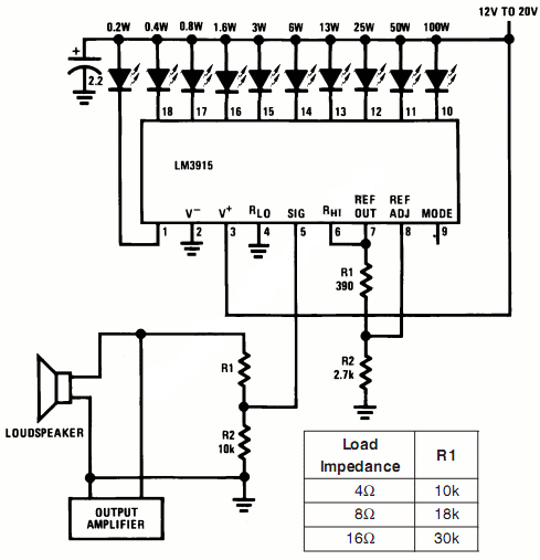
This is a simple schematic of audio power meter using LM3915 IC, this schematic can be used to measure the actual output power of your amplifier. For an audio engineer, this schematic Seems to be very helpful, especially for checking of sound system installation and field testing. Due to its logarithmic scale, the wide range of audio output with only ten scales cans Also be measured. If you take an attention to the pin number 5 of the LM3915, see That you will from the input is not yet Rectified. At this input pin, the negative swing will from the present. However, it is harmless since the current is limited by R1, the LM3915 earnest therefore respond only to positive cycle.
Power Meter Schematic Schematic of Power Meter For Audio Amplifier

Note:
When the speaker resistance is 4Ω, then, make R1=10kΩ, if the resistance of speaker is 8Ω, make R1=8kΩ, and if the resistance of speaker is 16Ω, make R1=30kΩ.

The absence of peak detector or the detector will of averages give the circuit a fast reading of instantenous power, and this Gives us insight of both average and peak condition. For more readable peak or average mesurement, you cans use peak or average detector circuit.

source : national semiconductor application notes

Rangkaian Ampere Meter Digital

type='html'>
This is a circuit of a digital ampere meter with 4 digit LED 7-segment display, the circuit capable of measuring the current consumption up to 10A with selected 100mA, 10mA and 1mA accuracy, and consumes only about 25mA of current. The ammeter is based on single ICL7107 chip and 3.5-digit seven segment LED displays. Due to a Relatively small number of components That the circuit is using it is possible to fit it on a small 3cm x 7cm printed circuit board.

Rangkaian Ampere Meter DigitalSkema Rangkaian Ampere Meter Digital

0.01 Ohm resistor should be made out of 1.5mm thick / 5cm long copper wire. 0.1 Ohm and 1 Ohm resistors should have 5W ratings.

For highest accuracy it is recommended that the ICL7107 ampere meter module should be supplied with its own voltage supply. If measurement of the current of the same supply is needed, ICL7107 ampere meter would have to sample negative not positive voltage supply.

Brightness of the LED displays can be varied by adding or removing 1N4148 small signal diodes that are connected in series. Use two 1N4148 diodes for higher brightness.

Also, the use of 7805 5V voltage regulator is highly recommended to prevent the damage of ICL7107 and 7660 ICs. .

Source: http://electronics-diy.com

High Voltage Meter or Probe Design

type='html'>
Common voltmeters, digital or analog, usually range to some hundred volts maximum. Higher voltages not only cannot be indicated, but will also destroy the instrument. However, the range of any voltmeter can easily be extended using extra series resistance, as shown in the figure. Calculating the necessary resistance implies knowledge of the input impedance of the voltmeter.

High Voltage Meter or Probe Circui
Circuit and formula for constructing high voltage probes. For example, let's assume we want to extend the range of a standard digital voltmeter (input impedance 10MOhm) to 100kV. The maximum DC voltage the meter can take is 1000V. This means we need an external 1GOhm high voltage resistor in series with the meter. The total voltage ios given by the value indicatedby the meter, times 100. If we wanted to read the voltage in kV directly, we would need a resistor 1000 times as large as the input impedance of the voltmeter, i.e. 10GOhm.

Such home-brew high voltage probes are good for DC only. For AC voltages, capacitive input impedance of the meter and capacity of the probe must be matched, which is difficult to achieve because of parasitic capacitance of the resistor chain. A few pF (the capacitance of a 1cm radius metallic sphere) make a big difference, especially at higher frequencies.

Source: kronjaeger.com

Sunday, June 24, 2012

10 LED VU Meter Using IC LM3914

This 10 LED VU meter circuit has only a few parts but is useful as an indicator for the measurement of entering acoustic signals. The circuit is a perfect one chip replacement for the standard analog meters. It is completely solid state and will never wear out
LM3914 VU Meter Circuit

The circuit is built around an LM3914 IC. The input signal from the VU meter is put on pin 5 of IC1. Through pin 9 of IC1 is the display mode sets (bar or dot instructions). In the drawn state IC1 works in the dot mode. When pin 9 is coupled to pin 3, the IC works in bar mode. Obviously the whole circuit consumes less power in dot mode.

List Component
C1 : 2.2uF/ 25V Electrolytic Capacitor
R1 : 1K Resistor
D1 : 1N4002 Diode
LED1-LED : 10 x LED or LED Array
U1 : LM3915 
 
Notes
  • V+ can be anywhere from 3V to 20V. 
  • The input is designed for standard audio line voltage with has a maximum input voltage of 1.3V.
  • Pin 9 can be disconnected from ground to make the circuit use a moving dot display instead of a bar graph display.