Showing posts with label Audio. Show all posts

Thursday, September 27, 2012

Software Cowon Jet Audio Plus v 8

type='html'>
Cowon Jet Audio Plus v8.0.1.7 Full version merupakan software multimedia yang dapat memutar file audio maupun video. Format yang dapat diputar pun sangatlah lengkap. Terdapat fitur Convert file audio dan Juga RIP CD. Banyak efek-efek suara yang terdapat pada aplikasi seperti X-Bass, Surround dan masih banyak lagi fitur lainnya yang tidak kalah dengan aplikasi pemutar suara yang populer seperti winamp. Bagi sobat yang ingin mencoba silahkan download ...


Screen Shoot :


Cowon Jet Audio Plus v8.0.1.7 Full version 32 MB
Features:
Supports All Major File Formats, Video Conversion, Audio CD burning, Recording, Tag Editing, Multi-channel sound ouput, Crossfade, Skin, Subtitles, Internet CD Database, Convenient album management & Playlist, Utilities, Remote Controller, Media Center Window, Audio Conversion, Audio CD Ripping, Internet Broadcasting, Various sound effects, Speed Control, Resume, Synchronized Lyric (Karaoke), Alarm & Timer, Equalizer, Superb Crystal-Clear Sound, Toolbar mode

Sunday, August 19, 2012

Rangkaian Audio tone control

type='html'>Bass-treble tone control circuits
Features:
  • Wide supply voltage range, 9V to 16V
  • Large volume control range, 75 dB typical
  • Tone control, ±15 dB typical
  • Channel separation, 75 dB typical
  • Low distortion, 0.06% typical for an input level of 0.3 Vrms
  • High signal to noise, 80 dB typical for an input level of 0.3 Vrms
  • Few external components required

Note: Vcc can be anything between 9V to 16Vand the output capacitors are 10uF/25V electrolytic.


the circuits provide some additional control over tone. They were origionally intended for use with synth modules but could be easily incorporated into most any effects circuit

Tree band aktiv tune control

A tone control circuit made with a single op-amp and having three ranges, bass, middle and treble controls.


Circuits of audio pre-Amp mic

type='html'>
A microphone preamp is a preamplifier used to amplify a microphone's low output voltage to a stronger, more usable level. A microphone preamp must provide stable gain for small signals without being sensitive to induced noise from cabling and without distorting large amplitude signals. Most microphones must be used in conjunction with a microphone preamp to function properly.

Simple audio Pre-Amp mic

This circuits use infront an RF oscilator to make an RF transmitter that is very sensitive to sound

Circuits of Audio Booster

type='html'>Audio booster with transistor


The 2N3392 transistor is a (cheap) low-power, low-noise and high-gain. If you wish to use a TUN, cross reference the parameters with one of the units from this list:

Potentiometer R5 of 100K is a linear type. The value of C1 may need to be between 0.05uF and 0.1uF (47nF/100nF). Experiment with the value for best performance.
Capacitor C3's working voltage should be at least 16V.

Friday, August 17, 2012

Skema Audio Ampflifier

type='html'> 60 watt Audio Amplifier

This circuit in the complete with bass-boost control on the fedback loop amplifier, this is done to overcome the declining quality of tone Bass. Graphic bass can reach a maximum at +16.4 dB @ 50Hz.

Note: Q3 and Q4 should be put in with the heatsinks.

Set the volume control on the position of the minimum and R3 with a minimum value resistansi also. try to switch the series and set up to R3 legible flow about 20 to 25mA.

Component List:

P1
P2
R2,4,8
R1
R3
R5
R6, 7
R9
R10
C1, 8
C2, 5
C3, 4
C6
C7
: 22k (Potesiometer)
: 100k (potensiometer)
: 820R 1/4W
: 4K7 1/4W
: 500R 1/2W
: 82K 1/4W
: 47K 1/4W
: 10R 1/2W
: 0,22 4W(wirewound)
: 470nF 63V
: 100uF/25V
: 470uF/25V
:47pF 63V
:10nF 63V
C9
D1
IC 1
Q1
Q2
Q3
Q4
J

: 100nF 63V
: 1N4148
: NE5532
: BC547B
: BC557B
: TIP42A
: TIP41A
: RCA Input


20 Watt Audio Amplifier


Circuit 20 Watt Audio Amplifier

Component List:

R1
C1,C2
C3
C4
C5
C6
U1
: 39K 1/4 watt
: 10 uF 25v
: 100 uF 25v
: 47 uF 25v
: 0.1 uF 25v
: 2200 uF 25v
: TDA1554


  • The circuit works best with 4 ohm speakers, but 8 ohm units will do.
  • The circuit dissipates roughly 28 watts of heat, so a good heatsink is necessary. The chip should run cool enough to touch with the proper heatsink installed.
  • The circuit operates at 12 Volts at about 5 Amps at full volume. Lower volumes use less current, and therefore produce less heat.

LM386 Audio Amplifier

This simple amplifier shows the LM386 in a high-gain configuration . For a maximum gain of only 20, leave out the 10 uF connected from pin 1 to pin 8. Maximum gains between 20 and 200 may be realized by adding a selected resistor in series with the same 10 uF capacitor. The 10k potentiometer will give the amplifier a variable gain from zero up to the maximum.

lm 3876/lm 3886 50 Watt Audio Amplifier

The 10 Ohm and 2.7 Ohm resistors must be 1 Watt types, and all others should be 1% metal film. All electrolytic capacitors should be rated at 50V if at all possible, and the 100nF (0.1uF) caps for the supplies should be as close as possible to the IC to prevent oscillation.

The supply voltage should be about +/- 35 Volts at full load, which will let this little guy provide a maximum of 56 Watts. To enable maximum power, it is important to get the lowest possible case to heatsink thermal resistance.

Wednesday, August 15, 2012

Rangkaian VU meter | Audio level Meter

type='html'>
Rangkaian VU meter is one of the monitor to see a top-level audio systems. VU meter display uses LED as its quick response time, operate at low voltage and small current, so kompatible with a series of integrated design.

Rangkaian
VU meter using the IC LM3915N which can control up to 10 LED. There are 10 fruit komparator that compares the input voltage level of the voltage reference (pin 6). In the IC has a reference voltage source is available so that you no longer need a reference voltage source from the outside.

To increase the voltage reference can be made with the setting VR2. Voltage reference that has been raised is not sensitive to changes in temperature and voltage portion. Reference voltage is used to control the voltage divider in the IC.

Rangkaian VU meters this series is quite simple, 1 IC and a few other supporting components. This series led the 10, the input voltage is 12V to 20 V but usually menggunkan voltage 12 Volt.

Skema rangkaian Vu meter

after a rangkaian of vu meters connected to the audio brace, brace maximize the volume of the audio, setting vr 10k so all led u.

Friday, August 10, 2012

Daftar Transistor Power Audio Daya besar

type='html'>
  • SANKEN TRANSISTOR MT200 -160V -4A 150W BCE Transistor, Type: SI-P, Voltage: 160 V, Current: 15 A, Power: 150 W, Frequency: 50 MHz
  • On Semiconductor NJL3281D (NPN) /NJL1302D (PNP) BIPOLAR POWER TRANSISTORS 15 AMP, 260 VOLT, 200 WATT The ThermalTrak family of devices has been designed to eliminate thermal equilibrium lag time and bias trimming in audio amplifier applications. They can also be used in other applications as transistor die protection devices.

List Transistor for high audio power amplifier

Tabel1.1
Model
ManuDescriptionVco(V)Ic(A)PD(W)hFE.fT(MHZ
shape.Complementary
2SA1215Sanken PNP160151505050MT2002SC2921
2SA1216Sanken PNP180172003040MT2002SC2922
2SA1295Sanken PNP230172005035MT2002SC3264
2SA1493Sanken PNP200151505020MT2002SC3857
2SA1494Sanken PNP200172005020MT2002SC3858
2SA1943Toshiba PNP2301515060302-21f1A2SC5200
2SB817Sanyo PNP1401210060 - 20015TO-3PB2SD1047
2SC2922SankenNPN18017200
50MT2002SA1216
2SC3857SankenNPN20015150
20MT2002SA1493
2SC5200ToshibaNPN23015150
302-21f1A
2SA1943
2SD1047SanyoNPN1401210060 - 200
15TO-3PB2SB817
MJ15003OnsemiNPN1402025025-1502TO-3
MJ15004
MJ15004OnsemiPNP
1402025025-1502TO-3
MJ15003
MJ15024OnsemiNPN
2501625015-604TO-3
MJ15025
MJ15025OnsemiPNP
2501625015-604TO-3
TIP36C
TIP35CSTNPN
1002512525-503TO-218TIP35C
TIP36CSTPNP1002512525-503TO-218Juned
TIP142STNPN-Darlington100101251000min
TO-218Juned
TIP147STPNP-Darlington100101251000min
TO-218Juned

Wednesday, August 8, 2012

Rangkaian Audio Mixer 3 Input

type='html'>
Many audio mixer circuits have been published but this this very simple audio mixer circuit uses only one transistor. The base emitter junction of the transistor is biased by the diodes D1 and D2.The signals to be mixed are directly coupled to the base of Transistor. Each input lines are current limited by using a 10k Potensiometer . With the used component values the collector current is around 1mA.
Audio MixerSkema Rangkaian Audio Mixer 3 Input

Notice:
  • The circuit can be assembled on a Vero board.
  • The circuit can be powered from 9-25V DC.
  • of each channel can be set using Variable resistor 10k

Transistors in the following series is enabled as a source of constant flow. By providing input audio signal on the emitter, the voltage on the emitter will fluctuate, which will cause the collector voltage also fluctuates. The amount of frequency fluctuation is comparable with the frequency of the incoming audio signal.

Skema LM3886 68 Watt Audio Power Amplifier

type='html'>Skema Rangkaian LM3886 68 Watt Audio Power Amplifier

The LM3886 is a high-performance audio power amplifier capable of delivering 68W of continuous average power to a 4 load and 38W into 8 with 0.1% THD+N from 20Hz-20kHz.

The performance of the LM3886, utilizing its Self Peak Instantaneous Temperature (°Ke) (SPiKe™) protection circuitry, puts it in a class above discrete and hybrid amplifiers by providing an inherently, dynamically protected Safe Operating Area (SOA). SPiKe protection means that these parts are completely safeguarded at the output against overvoltage, undervoltage, overloads, including shorts to the supplies, thermal runaway, and instantaneous temperature peaks.

The LM3886 maintains an excellent signal-to-noise ratio of greater than 92dB with a typical low noise floor of 2.0µV. It exhibits extremely low THD+N values of 0.03% at the rated output into the rated load over the audio spectrum, and provides excellent linearity with an IMD (SMPTE) typical rating of 0.004%.
 LM3886 68 Watt Audio Power Amplifier
Gambar Skema LM3886 68 Watt Audio Power Amplifier

Notice:
  • 68W cont. avg. output power into 4 at VCC = ±28V
  • 38W cont. avg. output power into 8 at VCC = ±28V
  • 50W cont. avg. output power into 8 at VCC = ±35V
  • 135W instantaneous peak output power capability
  • Signal-to-Noise Ratio >= 92dB
  • An input mute function
  • Output protection from a short to ground or to the supplies via internal current limiting circuitry
  • Output over-voltage protection against transients from inductive loads
  • Supply under-voltage protection, not allowing internal biasing to occur when |VEE| + |VCC| <= 12V, thus eliminating turn-on and turn-off transients
  • 11-lead TO-220 package
  • Wide supply range 20V - 94V
 LM3886 68 Watt Audio Power Amplifier

Saturday, August 4, 2012

3 led Level Audio amplifier Indicator

type='html'>
This circuit ican be used to show the power output level of any audio amplifier. The circuit is very simple and displays three power levels that can be set to any desired value. For a standard HiFi stereo power amplifier like the 25W MOSFET Audio Amplifier.

3 led Level Audio amplifier Indicator Skema Rangkaian 3 led Level Audio amplifier Indicator

Component List Of 3 led Level Audio amplifier Indicator

R1.................. 100K 1/4W Resistor
R2.................. 50K 1/2W Trimmer Cermet
R3.................. 330K 1/4W Resistor
R4.................. 1M2 1/4W Resistor
R5.................. 470K 1/4W Resistor
R6,R7............. 500K 1/2W Trimmers Cermet
R8.................. 1K5 1/4W Resistor
R9-R11............ 470R 1/4W Resistors
C1.................. 47pF 63V Ceramic Capacitor
C2.................. 100nF 63V Polyester Capacitor
C3.................. 47µF 25V Electrolytic Capacitor
C4.................. 1µF 25V Electrolytic Capacitor
D1.................. BZX79C5V1 5.1V 500mW Zener Diode
D2.................. 1N4148 75V 150mA Diode
D3-D5.............3mm. Yellow LEDs
IC1.................. LM339 Quad Voltage Comparator IC
SW1.................. SPST Slider Switch
B1.................. 9V

Other settings are possible IC1A is the input buffer, feeding 3 voltage comparators and LEDs drivers by means of a variable dc voltage obtained by R5 and C4 smoothing action. In order to achieve stability settings, the supply of IC1 and trimmers R6 & R7 is reduced and clamped to 5.1V by Zener diode D1.


About IC LM339

The LM139 series consists of four independent precision voltage comparators with an offset voltage specification as low as 2 mV max for all four comparators. These were designed specifically to operate from a single power supply over a wide range of voltages. Operation from split power supplies is also possible and the low power supply current drain is independent of the magnitude of the power supply voltage. These comparators also have a unique characteristic in that the input common-mode voltage range includes ground, even though operated from a single power supply voltage.

Application areas include limit comparators, simple analog to digital converters; pulse, squarewave and time delay generators; wide range VCO; MOS clock timers; multivibrators and high voltage digital logic gates. The LM139 series was designed to directly interface with TTL and CMOS. When operated from both plus and minus power supplies, they will directly interface with MOS logic- where the low power drain of the LM339 is a distinct advantage over standard comparators.


IC LM339 Applications

• High precision comparators
• Reduced VOS drift over temperature
• Eliminates need for dual supplies
• Allows sensing near GND
• Compatible with all forms of logic
• Power drain suitable for battery operation.

Friday, August 3, 2012

LED Indicator Daya Audio Amplifier

type='html'>LED Indicator Daya Audio Amplifier

This circuit, connected to the loudspeaker output of an audio amplifier, will indicate the instantaneous output power delivered to the loudspeaker(s) by means of six LEDs illuminating one after another by voltage values increasing little by little, providing the visual impression of a luminous bar or column, increasing and decreasing in height following the increase and decrease of the signal’s level.
Rangkaian Indicator Daya Audio Amplifier Skema Rangkaian Indicator Daya Audio Amplifier

Notes:
  • The output power indicated by each LED must be doubled when 4 Ohms loads are driven.
  • The circuit can be adapted to suit less powerful amplifiers by reducing the number of LEDs and related voltage dividers.
List Component :
R1: 220R 1/2W Resistor
R2,R5,R6,R8: 100R 1/4W Resistors
R10,R12,R14: 100R 1/4W Resistors
R3: 220R 1/4W Resistor
R4,R7: 330R 1/2W Resistors
R9: 560R 1/2W Resistor
R11: 820R 1/2W Resistor
R13: 1K2 1/2W Resistor

D1: 1N4004 400V 1A Diode
D2,D4,D6: BZX79C2V7 2.7V 500mW Zener Diodes
D3,D5,D7,D8,D9,D10 Red LEDs (Any dimension and shape) (See Notes)

The input signal is first rectified by D1 and then sent to six different voltage dividers, one for each LED. In this way, the indication provided by the LEDs illumination of this “Power Display”, will be related to the instantaneous power sunk by the whole loudspeaker cabinet. Six output power levels are displayed by the LEDs in a 2W - 80W range (no setup required). Each nominal power level indication into 8 Ohms load is reached when the respective LED illuminates at full brightness.

Audio Limiter Sederhana Untuk Power Amplifir

type='html'>Rangkaian Audio Limiter Sederhana Untuk Power Amplifir

This is a simple peak limiter - performance is quite respectable, and it can be used with conventional amps using bipolar transistors, MOSFETs, valves, etc, as well as BTL (Bridge Tied Load) amplifiers in car audio systems or for hi-fi. It will work with any amplifier from about 10W up to the highest power you are likely to encounter.

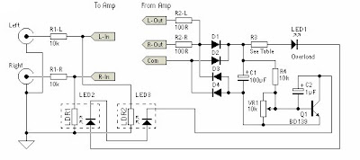
The gain control element is a Light Dependent Resistor (LDR). Once this point is reached, a very small increase in amplifier output voltage (and power) will cause the LED to provide much more light, reducing the value of the LDR, and thus reducing the input voltage. The effect is to keep the level more or less constant. This will prevent the amp from clipping (although a small amount on transients is unavoidable), and increase the apparent loudness because the signal is compressed.


The complete assembly must be totally shielded from light. I will leave the exact method to the individual constructor, but you might consider heatshrink tubing, a black 35mm film can, or anything else that comes to hand that is light proof. If metal, it must be earthed along with the shield around the light pipe - make sure that the LED leads are well insulated - a short to earth may damage the amp, and will almost certainly do something unpleasant and / or undesirable.


Audio Limiter Untuk Power AmplifirSkema Rangkaian Audio Limiter Untuk Power Amplifir


picture above shows the circuit of the unit. A 10k resistor was selected for the input, and although this is lower than I would like, many power amps have a relatively low input impedance and too much signal would be lost. The LDR simply shunts the signal to earth when it is illuminated. A single unit should control both channels of the power amp as shown. If only one channel is needed, then delete the components for "Right", including the associated light pipe. Use the input circuit shown in Figure 3 to improve limiting by using a higher input resistance.

IMPORTANT- If your amp is operating in bridge mode, the terminal marked "Com" must go to earth - not one or the other of the speaker leads. For automotive use (or any other single supply bridged amplifier), you must use two completely separate circuits, since the speakers operate with a quiescent voltage of about 7V above the chassis (earth) voltage, and there is no usable common terminal available.


The value of R3 must be selected based on the amplifier power. For a 100W amp, a value of 1.8k is about right, but it is likely that a little experimentation will be needed. As a rough guide, the table below will be helpful, and it is probable that the value from the table will be OK. The idea is to limit the current through the LED to a sensible maximum.

The polarity of the connection to the power amp output does not matter since a bridge rectifier is used. Very little current is drawn from the power amp output, and the whole circuit is self limiting, so it is not critical. When complete, advance the volume until you figure that this is a loud as you want the amp to be, and adjust the trimpot until the external LED just flashes. Use a multi-turn trimpot, as the setting is quite touchy. It could be made much less so, but at the expense of circuit flexibility.

Now, if you try to drive the amp harder, the external LED shows that the circuit is working, by flashing brighter, but the volume should remain quite stable. This can be checked with an oscilloscope (ideally), but otherwise just set it by ear. As more signal is driven into the amp, it may sound louder, but this is only because the input signal is being compressed.

Amplifier power in Table 1 for an 8 Ohm load. All diodes are 1N4004 or similar. The voltage rating on the caps should be 63V, and R2-L and R2-R should be rated at at least 1W. VR1 should be a multi-turn trimpot. High brightness LEDs will improve sensitivity and are recommended (but not essential).

Thanks to sound.westhost.com

Rangkaian Bass-Trable Audio Tone Control

type='html'>Rangkaian Bass-Trable Audio Tone Control

This is a simple tone control can be used in may audio applications. It can be added to amplifers, used as a stand alone control module, or even built into new and exciting instruments. It's one IC construction makes it a very compact circuit, as only a few support components are required. Plus, it does not use a dual power supply. This means that the circuit will run from 9V to 15V (although the bass will be a little weak at 9V).

IC LM1036 is controlled tone (bass/treble), volume and balance circuit for stereo applications in car radio, TV and audio systems. An additional control input allows loudness compensation to be simply effected. Four control inputs provide control of the bass, treble, balance and volume functions through application of DC voltages from a remote control system or, alternatively, from four potentiometers which may be biased from a zener regulated supply provided on the circuit. Each tone response is defined by a single capacitor chosen to give the desired characteristic.

Bass-Trable Audio Tone ControlSkema Rangkaian Bass-Trable Audio Tone Control

Note: Vcc can be anything between 9V to 16V and the output capacitors are 10uF/25V electrolytic.

Tone Control Features:
* Wide supply voltage range, 9V to 16V
* Large volume control range, 75 dB typical
* Tone control, 15 dB typical
* Channel separation, 75 dB typical
* Low distortion, 0.06% typical for an input level of 0.3 Vrms
* High signal to noise, 80 dB typical for an input level of 0.3 Vrms
* Few external components required

Thursday, August 2, 2012

Rangkaian Audio Limiter Berbasis Op-Amp

type='html'>
Audio Limiter Berbasis Op-Amp

This audio peak limiter employs a FET as a variable resistance to attenuate the input signal according to a control voltage (CV). It offers unusually good performance with low cost and component count. A TL072 dual opamp (U1) provides the circuit gain and full wave peak detection.


Audio Limiter Berbasis Op-AmpSkema Rangkaian Audio Limiter Berbasis Op-Amp


If desired, a LED VU meter may be used here instead, and with proper calibration will give a good indication of the peak attenuation at any time. This option will require some experimentation from the constructor, and further details are up to the individual to work out.

The 4.7K resistor and 1uF capacitor (R14 and C5) determine the attack time, which is about 5ms as shown. R12 and C5 determine the release or recovery time, and as shown this is approximately 1 second.

R11, C3 C4 and R13 form the distortion cancelling circuit, and as can be seen, the control voltage impedance is very low compared to the distortion cancellation impedance, so the circuit's attack time is not compromised. The values of resistance and capacitance have been optimised for the least distortion across the audio band, at 0.3% THD typical for frequencies above around 500 Hz, at 1.65V RMS output level. Below 500 Hz, the distortion rises gently with decreasing frequency, but also falls with lower voltages. Distortion is negligible at any voltage level below the limiting threshold.

Be careful of values for R14 of less than 1k, as the opamp will be unable to supply the current needed to charge C5. R13 (3k) is easily made using a 1k2 and 1k8 resistor in series. C5 needs to be a low leakage capacitor - either a low leakage electrolytic or a tantalum. A standard electro is inappropriate for this circuit.

In addition, always keep R12 a minimum of 10 times R14 ... for example, if R14 were to be 1k, the minimum value for R12 will be 10k. This would be a very fast limiter indeed

Saturday, July 21, 2012

Rangkaian 8Watt Audio Amplifier TDA2030

type='html'>Audio TDA2030

This is a circuit of 8-watt audio amplifier IC TDA2030-based mono. When you use 4 ohm speakers then you get 14 watts output power, and around 8 watts if you use 8 ohm loudspeaker.

audio amplifier TDA2030Skema rangkaian audio TDA2030


Although the TDA2030 is capable of delivering 20 watts of audio power, I deliberately reduced the output to about 8 watts to 10 watts drive speakers. This is more than adequate for a smaller room. Input sensitivity is 200mV. Higher input levels naturally will give greater output, but no distortion should be heard. The gain is set by the 47k and 1.5k resistors. The TDA2030 IC is affordable and makes a good replacement amplifier for low to medium audio power systems. Incidentally, it is speaker efficiency that determines how "loud" the sound is. Speaker efficiency or sound pressure level (SPL) is usually quoted in dB / meter. A speaker with an SPL of 97dB / m will sound louder than a speaker with an SPL of 95dB / m.


Absolute Maximum Ratings IC TDA2030

Supply voltage ± 18 (36) V
Input voltage Vs
Differential input voltage ± 15 V
Output peak current (internally limited) 3.5 A
Power dissipation at Tcase = 90°C 20 W
Tj Stoprage and junction temperature -40 to 150 °C

IC TDA2030 pinning

Kit Amplifier TDA2030

Rangkaian Audio Tone Control 2 Transistor

type='html'>Audio Tone Control 2 Transistor

Audio tone control circuit based transistors on these provides a maximum cut and boost of around 10dB at 10K and 50Hz.
audio tone control 2 transistorSkema rangkaian audio tone control 2 transistor


The first BC109C transistor is acting as a buffer. It provides the circuit with a high input impedance, around 250k has a voltage gain of slightly less than unity. As the Baxendall tone control circuit is a passive design, all audio frequencies are attenuated. The position of the controls and reactance of the capacitors alters the audio response. The last transistor provides a slight boost of about 3x. The output is designed to feed an amplifier with input impedance of 10k to 250k. Both tone controls should be linear type Potentiometers.


quick Data Transistor BC109C

Low current max. 100 mA
Low voltage max. 45 V
Collector-base voltage open emitter 30 V
Collector-emitter voltage open base - 20 V
Peak collector current - 200 mA
total power dissipation Tamb £ 25 °C - 300 mW
DC current gain (hFE ) IC = 2 mA; VCE = 5 V 200 - 800
transition frequency IC = 10 mA; VCE = 5 V; f = 100 MHz 100 - MHz


Pining transistor BC109C


1 emitter
2 base
3 collector, connected to the case

Tuesday, July 17, 2012

USB Audio Interface berbasis DAC PCM2902

type='html'>Rangkaian USB Audio Interface

This is high quality Preamplifier circuit with built-in USB DAC for my power amplifier Leachamp. Schematics is from datasheet of PCM2902. Circuit includes DAC and ADC, SPDIF output and input and HID part with 3 buttons for MUTE, VOL + and VOL-.

For high quality playback is needed to use an external low-drop voltage stabilizer for the DAC part. DAC is used LP2951CM which was easily available at local stores. Output voltage is set to about 3.7V with two resistors. Circuit board is designed regarding to good ground placement and separating of analog and digital ground. These ground are connected in one point at a USB connector.

Rangkaian USB Audio Interface Skema Rangkaian USB Audio Interface


In datasheet of PCM2902 is recommended to connect Low Pass Filter to output of DAC for filtering high frequencies above audioband which are produced by oversampling conversion. Integrated circuit includes digital LPF which filters frequency above 100kHz. In application notes for filter on the manufacturer pages are recommended 1st-Order LPF (simple RC) or 2nd-Order with operation amplifiers which works like preamplifier too. I used simple RC LPF with recommended values R 1k and C 4n7. It's better to use roll-type capacitor instead ceramic. I didn't hear difference in a sound between connection with filter or without it, but with respect to other components in a audio chain it is better to use it. For a higher cut-off frequency we can change value of capacitor to 3n3.


Rangkaian Peredam Noise Audio (DNR system )

type='html'>Peredam Noise Audio (DNR system )

This circuit can be use to audio noise reduction for use with audio playback systems. The DNR system is noncomplementary, meaning it does not require encoded source material. The system is compatible with virtually all prerecorded tapes and FM broadcasts. Psychoacoustic masking, and an adaptive bandwidth scheme allow the DNR to achieve 10 dB of noise reduction. DNR can save circuit board space and cost because of the few additional components required.

 Rangkaian Peredam Noise Skema Rangkaian Peredam Noise Audio (DNR system )

PCD layout DNR system

Features
  • Non-complementary noise reduction, “single ended”
  • Low cost external components, no critical matching
  • Compatible with all prerecorded tapes and FM
  • 10 dB effective tape noise reduction CCIR/ARM
  • weighted
  • Wide supply range, 4.5V to 18V
  • 1 Vrms input overload
Applications
  • Automotive radio/tape players
  • Compact portable tape players
  • Quality HI-FI tape systems
  • VCR playback noise reduction
  • Video disc playback noise reduction
Note:
The circuit system should always be placed before tone and volume controls. Placing DNR system after tone or volume control won’t work because any adjustment of these controls would alter the noise floor seen by the DNR control path.

Sunday, July 15, 2012

Rangkaian Audio Signal Injector|Tracer

type='html'>
This circuit can be used as a signal injector or signal tracer. This circuit is very helpful in trouble shooting audio circuits, when you need to test a circuit by injecting a signal and observe the output (by watching the oscilloscope or by hearing the loudspeaker ), or by tracing some points inside the circuit when an audio signal is applied to the input.

Rangkaian Audio Signal Injector|TracerSkema Rangkaian Audio Signal Injector|Tracer

The circuit uses supply from 9 volts battery. An alligator clip is recommneded for the ground probes, so you can works with one hand to hold the board, and the other hand to target the test probes. The SPDT switch connected to the transitor and the earpiece is used to select the function, whether as a signal or a signal injector tracer.


Transistor 2n3904

This transistor is designed as a general purpose amplifier and switch. The useful dynamic range extends to 100 mA as a switch and to 100 MHz as an amplifier.
Transistor 2n3904 Pin

Absolute maximum rating
  • Collector-Emitter Voltage 40 V
  • Collector-Base Voltage 60 V
  • Emitter-Base Voltage 6.0 V
  • Collector Current - Continuous 200 mA
  • Operating and Storage Junction Temperature Range -55 to +150 °C

Saturday, June 30, 2012

Rangkaian Audio Mixer 6 Channel

type='html'>
Audio Mixer 6 Channel

The following is a main of the mixer-6 Ch circuit. The circuit constituted by six input channels. The channels are from monophonic channels CH 1-4 and CH 5-6, are intended for stereo use. The number of input channels they want as long Itself Can Increase You Want.
rangaian audio mixer 6 channelSkema rangaian audio mixer 6 channel

The output of Each channel drives the RV1-6, that regulation potesometer level of sound. With RV7-12 We create conditions of balance Between two channels (BALANCE). All the signals from the input channels in this point are added by two adders [IC1a-b], for Each channel Here exist two Trimmer TR1-2 That adjust the gain of Each IC, adapting the level of signal of the output, in the level That We Want. They Can be suppressed if you do not need something and Standard and Poor. The next stage is a equalizer, three bands of regulation. The IC3α-b, constitute the output of the mixer, they want a one acre have gain and they want the make the essential isolation of the previous stages, with the unit That We Will drives. For whoever they want want they want use headphones, it exists a classic circuit drive of headphones, round the IC2a-b, that give the output in the JF13. It Can Also Also exist optical clue of audio levels, with a stereo VUMETER.

List component
  • R1-12=4.7Kohms
  • R13-24=10Kohms
  • R25-26=22Kohms .
  • R27-30-34-39=100ohms
  • R28-29-36-37=100Kohms
  • R31-42=10Kohms
  • R32-41=4.7Kohms
  • R33-40=10Kohms
  • R35-38=47ohms
  • RV1....4=47Kohms Log.
  • RV5-6-13=2X47Kohms Log.
  • RV7....12=10Kohms Lin. pot. Log
  • C1....8=10uF 25V
  • C9-11=47pF ceramic or mylar
  • C10-12=47uF 25V
  • C13-14=100uF 25V
  • C15-16=2.2uF 16V
  • C18-21=100pF ceramic or mylar
  • C19-20=220uF 25V
  • TR1-2=4.7Kohms trimmer
  • Q1-3=BD139
  • Q2-4=BD140
  • IC2=NE5532 - TL072
All the Resistors is 1/4W 1% metal film C18-21=100pF ceramic or mylar

for more detail read here