Showing posts with label Rangkaian. Show all posts

Sunday, September 23, 2012

RANGKAIAN SKEMA LAMPU LED RUMAH 20 WATT

Skema Lampu LED Penerangan Rumah 20 Watt setara Lampu Pijar 100 Watt
RANGKAIAN SKEMA LAMPU LED RUMAH 20 WATT
Kita mengetahui bahwa lampu pijar digati dengan lampu neon hemat energi, tetapi sekarang kecenderungan produsen lampu akan memproduksi lampu dengan komponen lampu LED. Kelebihan dari lampu LED adalah : umur lampu lebih lama , lampu LED memiliki umur 50.000 jam. Bila menggunakan lampu selama 5 jam sehari, mereka akan bertahan setidaknya 15 tahun. Lampu LED tahan goncangan dan tidak mengandung zat berbahaya. Dalam lampu LED tidak ada radiasi ultraviolet dan inframerah, serta bebas kedip, membuat mereka tidak berbahaya untuk mata. Dan yang paling menguntungkan adalah konsumsi daya listrik sangat kecil. Konsumsi daya dari lampu LED 10 watt adalah sebanding dengan terangnya lampu pijar dengan kapasitas 100 watt.

Skema rangkaian lampu led tersusun dari Kapasitor 0.2 mk , nilai kapasitansi adalah dipilih sedemikian rupa sehingga arus yang melalui LED tidak melebihi 25 mA. Tujuan utama dari kapasitor 10 MK untuk penstabil tegangan , jembatan dioda VD1-VD4. Resistor 1k untuk membatasi arus yang melalui garis LED. Untuk penempatan dapat dipasang tergantung keinginan anda. Keuntungan lampu led ini tahan panas dan nyalanya leih terang

Sunday, August 19, 2012

Rangkaian Audio tone control

type='html'>Bass-treble tone control circuits
Features:
  • Wide supply voltage range, 9V to 16V
  • Large volume control range, 75 dB typical
  • Tone control, ±15 dB typical
  • Channel separation, 75 dB typical
  • Low distortion, 0.06% typical for an input level of 0.3 Vrms
  • High signal to noise, 80 dB typical for an input level of 0.3 Vrms
  • Few external components required

Note: Vcc can be anything between 9V to 16Vand the output capacitors are 10uF/25V electrolytic.


the circuits provide some additional control over tone. They were origionally intended for use with synth modules but could be easily incorporated into most any effects circuit

Tree band aktiv tune control

A tone control circuit made with a single op-amp and having three ranges, bass, middle and treble controls.


Friday, August 17, 2012

Skema Rangkaian Oscillator LM555

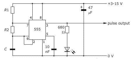
type='html'>LM555 Astable oscillator Circuit.
Circuit oscillator astable

Frequency of the output pulses is determined by the values of two resistors, R1 and R2 and by the timing capacitor, C.

To calculate the frequency (F):

To calculate the the On time or Off time:

Before calculating a frequency, you should know that it is usual to make R1=1 kΩ because this helps to give the output pulses a duty cycle close to 50%, that is, the HIGH and LOW times of the pulses are approximately equal.

LM555 Monostable oscillator Circuit.
circuit oscillator monostable

Trigger input is held HIGH by the 10 kΩ pull up resistor and is pulsed LOW when the trigger switch is pressed. The circuit is triggered by a falling edge, that is, by a sudden transition from HIGH to LOW. The trigger pulse, produced by pressing the button, must be of shorter duration than the intended output pulse.

To calculate the period (t):

Thursday, August 16, 2012

Rangkaian UPS sedehana

type='html'>
Uninterruptible power supply (UPS), also known as a battery back-up, provides emergency power and, depending on the topology, line regulation as well to connected equipment by supplying power from a separate source when utility power is not available. It differs from an auxiliary or emergency power system or standby generator, which does not provide instant protection from a momentary power interruption. A UPS, however, can be used to provide uninterrupted power to equipment, typically for 5–15 minutes until an auxiliary power supply can be turned on, utility power restored, or equipment safely shut down.

While not limited to safeguarding any particular type of equipment, a UPS is typically used to protect computers, data centers, telecommunication equipment or other electrical equipment where an unexpected power disruption could cause injuries, fatalities, serious business disruption or data loss.

picture below is a simple series of UPS. This series UPS has a power of 60W (if the transformer is used more, the power output of the UPS is also greater).

UPS
Gambar Skema Rangkaian UPS

description :
Transformer: Min 4 ampere or more
Diode|Dioda: Min 5 ampere or more
Irfz 44: Paste cooling plate


When normal PLN Electricity, of the adapter (the series of the most left) will produce voltage 12 - 13 volt / 5 ampaere. This voltage is used to fill mengoprasikan UPS batery and therefore this UPS if you plan to load a higher modifikasilah of this series that have a higher ampere. PLN electricity when dead, the source voltage in the switch to akan bateray

When electricity PLN suppressed, the source voltage will switch to the battery. ups that may be living longer while the power off, use battery who have ampere / hour high (large) or can also install some of the ways in parallel battery

Wednesday, August 15, 2012

Rangkaian Volt Meter Digital sederhana

type='html'>

Digital voltmeters are instruments that measure voltage or voltage drop in a circuit. They use solid-state components and display values digitally. Typically, digital voltmeters (digital volt meters) are used to locate excessive resistance that may indicate an open circuit or ground. They are also used to identify low voltage or voltage drops that may indicate a poor connection. Digital voltmeters are connected in parallel (and never in series) with the circuit being tested so that the meter can tap a small amount of current. The positive lead is connected to the circuits positive side and the negative lead is connected to the circuits ground. The digital voltmeters internal resistance is the impedance, which is usually expressed in ohms per volt. This amount is relatively high in order to prevent the device from drawing significant current and disturbing the operation of the circuit being tested. The sensitivity of the current meter and the value of the series resistance determine the range of voltages that digital voltmeters can measure.

Digital voltmeters can measure a range of alternating current (AC) voltages, direct current (DC) voltages, or both AC and DC voltages. Devices typically display between three and seven digits. Some digital voltmeters can capture minimum and maximum voltages called spike readings.

In the picture below is a series of simple digital voltmeter using the Seven-segment display, this series based ICL7107.The ICL7107 is a 3 1 / 2 digit LED A / D convertor. It contains an internal voltage reference, high isolation Switches analog, sequential control logic, and the display drivers. The auto-zero adjust ensures zero reading for 0 volts input.
Rangakaian Voltmeter digitalGambar skema Rangkaian Voltmeter digital

Rangkaian game 7-segmen

type='html'>Rangkaian game 7-segmen
Skema Rangkaian game 7-segmen

You can play this game alone or with your friends. The circuit comprises a timer IC, two meters of decade and a driver of posting with a posting of segment 7. The play is simple. Like city above, it is a play of marking and the competitor which marks 100 points quickly (in short stages) is gaining it. To mark, one with the option to press the S2 switch or S3. Commutate S2, once pressed, realize against counting in the direction forwards, whereas the S3 switch helps to count in bottom. Before beginning a fresh play, and for this matter even a fresh movement, you must press on the S1 switch to give to zero the circuit. Then, press on the two switches the ones of, C. - with-D. S2 or S3. On pressing on the switch S2 or S3, the exits of the BCD of the meter change very quickly and when you release the switch, last remainders of number locked with the output of IC2. The locked number of BCD entered the BCD to the decoder of 7 segments/au conducting IC3 which leads a posting DIS1 of common-anode. However, you can read this number only when you press on the S4 switch. The order of the operations to play the (Rangkaian game 7-segmen) game enters, indicate that the `X of two players and Y, are recapitulated below:

  • The `X of player starts by pressing temporary contact STRONG CURRENT S1 followed by pressing and release of the S2 switch or S3. Then it supports on the S4 switch to read posting (points) and of the notes in bottom of this number (known as X1) manually.
  • The `Y of player also starts by pressing temporary S1 switch followed by the pressing of the S2 switch or S3 and note then in bottom of its points (known as Y1), after having pressed on the S4 switch, exactly of the same mode as made by the first player.
  • The `X of player still presses on the S1 switch and repeats the stages shown in stage 1 above and the notes in bottom of its new points (said, X2). He adds these points to his preceding points. The same process is repeated by the `Y of player in his turn.
  • The play continues up to the points reached by one of the two totals of players until or exceeds 100, to be declared as gaining.
  • Several players can take part in this play, with each one which obtains a chance to mark during its own turn. The assembly can be made using a universal council. Fix posting (LED and posting of segment 7) on the box with the three switches. The supply voltage for the circuit is 5V

Rangkaian Penguat Tak Membalik/Differensial Op Amp 741

type='html'>Penguat Operasional (Operasional Amplifier)

Brace OPERATIONAL (OP-AMP) is a series of integration (IC) that is capable of linier provide the very large and can be operated at intervals voltage which is quite big. Op-amp to be able to give up at the 100,000 for an op-amp in a series of open-Hubung until only of 1 (one) time when the cohort is used as a series of voltage (voltage FOLLOWER).


Penguat Tak Membalik

The following circuit schemes is an Op Amp is applied in a non-inverting amplifier mode, the output voltage (Vo) has the same phase with the input voltage (Vi). From the way the arrangement can be seen that the input signal is connected to input non-inverting Op-Amp, so the output signal has the same phase with the input signal.
Skema Rangkain Penguat Tak Membalik

As shown in the picture sequence above, the output voltage has the same phase with voltage inputs. The amount of strengthening the non-inverting circuit is determined from a comparison of the value of R1 and R2. Resistors R1 and R2 form a resistive divider network to provide the feedback voltage (VA) are needed to reverse the input.

Show that the gain of the amplifier is:
Output voltage can be calculated using the following formula:

Penguat Differensial

Penguat Differensial is a brace which the output voltage Vo is or is the result of the difference between the two voltage inputs on the terminal non-inverting and inverting it. General formula that applies to brace differensial is as follows:
Rangkaian differensial brace shown in Figure below.

 Penguat Differensial

Rangkaian Kunci Digital Ber-password

type='html'>
LS7220 is a MOS digital lock circuit. When wired to a ten-digitkeypad, the circuit will recognize one four-digit combination out of a possible 5040 combinations. The LS7220 is configured with the features required for an Automotive Ignition Anti-Theft Digital Lock (See Figure 5). These
features include Sense input which enables the IC, Save Memor for Valet Parking, Convenience Delay to maintain Unlock condition for short term interruptions of the Sense input and Save Status and Lock Status outputs which can be used for direct drive of LED indicators.

following simple example the use of LS 7220 as Electronic Combination Lock
Rangkaian Kunci Digital Ber-password
Skema Rangkaian Kunci Digital Ber-password


List komponen Electronic Combination Lock
  • C1 1uF/25Vr
  • C2 220uF/25V
  • R1 2.2K
  • Q1 2N3904 NPN Transistor 2N2222
  • D1 1N4148 Rectifier Diode
  • K1 12V SPDT Relay, Any appropriate relay with 12V coil
  • U1 LS7220 Digital Lock IC
  • S1-S12 PST Momentary Pushbutton
  • HD1 12 Position Header
Rangkaian Kunci Digital Ber-password is the circuit diagram of a simple electronic combination lock usingLS 7220. Rangkaian Kunci Digital Ber-password Password Digital can be used to activate a relay for controlling (on & off) any device when a preset combination of 4 digits are pressed.The circuit can be operated from 5V to 12V.

To set the combination connect the appropriate switches to pin 3,4,5 and 6 of the IC through the header.As an example if S1 is connected to pin 3, S2 to pin 4 , S3 to pin 5, S4 to pin 6 of the IC ,the combination will be 1234.This way we can create any 4 digit combinations.Then connect the rest of the switches to pin 2 of IC.This will cause the IC to reset if any invalid key is pressed , and entire key code has to be re entered.

When the correct key combination is pressed the out put ( relay) will be activated for a preset time determined by the capacitor C1.Here it is set to be 6S.Increase C1 to increase on time.

For the key pad, arrange switches in a 3X4 matrix on a PCB.Write the digits on the keys using a marker.Instead of using numbers I wrote some symbols!.The bad guys will be more confused by this.

Rangkaian VU meter | Audio level Meter

type='html'>
Rangkaian VU meter is one of the monitor to see a top-level audio systems. VU meter display uses LED as its quick response time, operate at low voltage and small current, so kompatible with a series of integrated design.

Rangkaian
VU meter using the IC LM3915N which can control up to 10 LED. There are 10 fruit komparator that compares the input voltage level of the voltage reference (pin 6). In the IC has a reference voltage source is available so that you no longer need a reference voltage source from the outside.

To increase the voltage reference can be made with the setting VR2. Voltage reference that has been raised is not sensitive to changes in temperature and voltage portion. Reference voltage is used to control the voltage divider in the IC.

Rangkaian VU meters this series is quite simple, 1 IC and a few other supporting components. This series led the 10, the input voltage is 12V to 20 V but usually menggunkan voltage 12 Volt.

Skema rangkaian Vu meter

after a rangkaian of vu meters connected to the audio brace, brace maximize the volume of the audio, setting vr 10k so all led u.

Skema Rangkaian Sirine Polisi

type='html'>Rangkaian sirine police will produce sound that is almost similar to the sirens and the police can plug in the car or motorcycle. Rangkaina consists of 2 pieces IC NE 555 that serves as the frequency (multivibrator astable) that the frequency can be set to play Vr1 and Vr2.
Skema Rangkaian Sirene Polisi
Gamabar Skema Rangkaian Sirine Polisi

If the sound output in the less hard (loud) you can add a brace power amplifier that has a higher brace misalanya series amplifier LM386. series has a power output greater tegangn and have the same input. To install this series you just menghubungakan output rangkain sirens and then enter in to the input. Move the speaker to the output ampilifier LM386


functions of each pin IC 555:

IC 555 pic

  • Ground, is the input pin of the source of the negative DC voltage
  • trigger, negative input from the lower comparators (comparator B) that maintain oscillation capacitor voltage in the lowest 1 / 3 Vcc and set RS flip-flop
  • output, the output pin of the IC 555.
  • reset, the pin that serves to reset the latch inside the IC to be influential to reset the IC work. This pin is connected to a PNP-type transistor gate, so the transistor will be active if given a logic low. Normally this pin is connected directly to Vcc to prevent reset
  • control voltage, this pin serves to regulate the stability of the reference voltage negative input (comparator A). This pin can be left hanging, but to ensure the stability of the reference comparator A, usually associated with a capacitor of about 10nF to berorde pin groun
  • threshold, this pin is connected to the positive input (comparator A) which will reset the RS flip-flop when the voltage on the capacitor from exceeding 2 / 3 Vc
  • discharge, this pin is connected to an open collector transistor Q1 is connected to ground emitternya. Switching transistor serves to clamp the corresponding node to ground on the timing of certain
  • vcc, pin it to receive a DC voltage supply. Usually will work optimally if given a 5-15V. the current supply can be seen in the datasheet, which is about 10-15mA.

Rangkaian Pendeteksi kebocoran Gas

type='html'>
series of gas leak detection is a series of very useful to reduce the fire hazard in the leakage of gas sebabkan karna. karna time series to detect the existence of this gas, will enable a series of alarms or lights as a sign of danger. this series is suitable in use in the cost of housing karna perakitannya relatively cheap and simple. This alarm uses a gas sensor (TGS 815) that will detect the existence of gas. detection results will affect the relay

Skema Rangkaian Pendeteksi kebocoran gas
Gambar skema rangkaian pendeteksi kebocoran gas

description :
D1-d5: Diode Min 0.5 Ampere
Transformer (Trafo): 0-12 volt 0.5 Ampere
Z: Diode Zener 5,1Volt/0.5 watt
For the other as written in the series scheme

In this series of detention sensor will change when there is leakage. With changes in the value of this detention, the transistor base voltage will be changed (increased base voltage) so that the transistor T1 to be active. when the transistor T1 on, SCR get rigger so SCR on and relay active (change kutup). This relay can be used to control the lights, sirens or ALRM as if there is leakage of gas

this series work better if, in the place near the gas tube. so that in case of gas leakage, can know more in early

Rangkaian Speaker Protection|Pengaman

type='html'>
Circuit of speaker protekter this work to provide protection speaker from the dc leakage currents and also to protect the audio amplifier in the case of a short relationship
This Circuit also has advantages, namely: the case of consleting relationship with the speaker amplifier series will be lost directly, so that the speaker's safe to fire.time waiting or delay time is about 5 seconds, and can be changed with the change elco condenser C2 to the value of smaller. The time needed to open the relay back when the flow to be around 0.5 seconds. Or you can try using a series of under this scheme:

Circuit Diagram Of Speaker Protection

Speaker Protection
Skema Rangkaian Speaker Protection

R1=22Kohm C4-5=100uF 25V IC1=TL071
R2-3=390Kohm Q1=BC560C RL1=Relay 12VDc Omron G2R2
R4=470Kohm Q2-3-4=BC550C J1=3pin connector with 2.54mm step
R5=1Mohm Q5=BD139 J2=2pin connector with 2.54mm step
R6-7-8-9-10-12=10Kohm D1-2-3=1N4148 J3=2pin connector with 3.96mm step
R11=820 ohm D4=Green 5mm Led
C1-2-3=47uF 63V D5=Red 5mm Led

Monday, August 13, 2012

Rangkaian 10 Led Sound Meter

type='html'>
Rangkaian 10 led ini function to indicate the height level of sound, which in the show led with a flame Supply voltage is needed in the series is 3V to 20V. 10 led work if audio voltage into a series of valuable 1.3 volt

Rangkaian 10 Led Sound Meter using the IC LM3915N which can control up to 10 LED. There are 10 fruit komparator that compares the input voltage level of the voltage reference (pin 6). In the IC has a reference voltage source is available so that you no longer need a reference voltage source from the outside.

To increase the voltage reference can be done with installing resistor R1 and R2 (picture 1). Voltage reference that has been raised is not sensitive to changes in temperature and voltage portion. Reference voltage is used to control the voltage divider in the IC

Signal input (audio signal) should be first in the right direction, just half a wave, then enter pin 5. Signal input into the face of the brace by TR-1. Voltage that has been and is supported by a series of buffer TR-2. Output signal is taken from emiter TR-2 and a half in the direction the waves by D11, and filtered by R6, C4, and R8.

The level of input made by trimpot P1. 8-pin in the ground, so the reference voltage on pin 8 output of 1.25 volt (minimum) references provided in the high (pin 6). So that the flow out of the pin 7 is big enough to light a LED, then R9 is made quite small (390 ohm). Installation of C6 to prevent oscillation arising due to voltage LED is not filtered. S1 is a switch for selection of "fast" or "slow.
Rangkaian 10 Led Sound MeterGambar Skema rangkaian 10 Led Sound Meter

Rangkaian 10 Led Sound Meter can be driven from the output deck. Pre-amp (tone control), or the output from the speaker. To continue from the speaker, given the custody of reducer 1 M ohm so that the incoming signal to a series of not too large. Settings range from the LED is done on the trimpot P1

components List.
  • R1 = 2k2 C1 = C3 = C5 = C6 = 2,2uF/16V
  • R2 = 1M5 C4 = 0,47uF/10V
  • R3 = 15k L1…L10 = LED
  • R4 = 220k D11 = IN4148
  • R5 = 2k7 T1 = T2 = 2SC828
  • R6 = 47 ohm IC = LM3915N
  • R7 = 10 ohm
  • R8 = 100k
  • R9 = 390 ohm
  • VR = 100k trimpot

Teorema Superposisi untuk Analisi Rangkaian DC

type='html'>
Teoerma This states that the size of the current or voltage in an electrical element in the series can be determined by considering the contribution from each source independently. At the time we consider the contribution from a source other then the source eliminated. Thus eliminated voltage source (V = 0) into a series of short relationships. While to eliminated current source (I = 0) into a series of open relationship. Large currents or voltages in the series who want to search the Answer algebraically from current or voltage due to contributions from each source. With these theorems we shall consider the flow direction or polarity of the voltage at the figure donations from each source.

  • Example
By using the theorems superposisi, specify the size of the flow (I) through the R2 in the following series!
Teorema Superposisi untuk Analisi Rangkaian DC

Answer:
Taking account of Cash from the voltage source E1, the source voltage E2 to be eliminated so that a series of short relationships, such as the image below:
Teorema Superposisi untuk Analisi Rangkaian DC

By using the principle Flow distributor, illicit flow of E1 can search on:
Teorema Superposisi untuk Analisi Rangkaian DC

Taking account of Flow E2 from the voltage source, voltage source E1 to be eliminated so that a series of short relationships, such as the image below:
Teorema Superposisi untuk Analisi Rangkaian DC

By using the principle Flow distributor, illicit flow of E2 can search on:
Teorema Superposisi untuk Analisi Rangkaian DC

So: Flow through a total reaktansi Answer R2 is a contribution of each source (cash donation dri E1 and E2) that is equal to:
I = I '+ I "= 1A = + 0.25 A 1.25 A

Teorema Millman-Analisis Rangkaian DC

type='html'>Teorema Millman untuk menganalisis Rangkaian DC

Milman theorems is that a number of series voltage source is connected with the parallel resistor can be simplified to a voltage source only.
Teorema Millman
Steps to apply theorems milman this is as follows:

1. Change all the source currents are a source of tension with the principle of source transformation. So he sets up as follows below
Teorema Millman

2. Determine the total current magnitude Answer algebraic flow from all sources so that there will be a series:
Teorema Millman

3. Change the source of these flows, to be the source voltage by using the principle of source transformation.
Teorema Millman

In general theorems Millman formulated
Teorema Millman

If in the series there are a number of sources of electricity flow parallel with the resistor connected in series, then themillman theorems will be :
Teorema Millman

Teorema Millman


  • Example 1
Specify the string Millman, of the following series!
Teorema Millman

Answer:
specify millman first strand, which is connected with the resistor R3
Teorema Millman

So that the series is to be:
Teorema Millman


  • Example 2.
By using the theorems Millman, specify the current that flows in R3!

Teorema Millman

Answer:
specify millman first strand is connected with the resistor R3:
Teorema Millman

So that the series is to be:
Teorema Millman

Thus, large currents I (Flow R3) can be determined with the Ohm law:
Teorema Millman

  • Example 3
Specify millman strand of a series between the terminals ab in the picture below!
Teorema Millman

Answer:
Teorema Millman

Millman rope so that it is as follows:
Teorema Millman

Teorema Norton-Analisis Rangkaian Listrik

type='html'>
Teorema Norton untuk menganalisis Rangkaian listrik DC

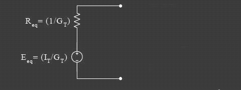
Norton theorems is that, any two of the series can be converted into an equivalent set of which consists of a current source (IN) and a norton equivalent resistans (RN) with a source flow dipararel it.

Steps to find the rope it is:
1. Specify two of the series who want to search string norton.

2. Determine the amount of the cash flow it is that flows between two terminals in the series who want to search string norton. Because we want to explore the current two terminals must be linked to a series of short first so you can cash flow.

3. Specify the size of the resistans norton is the equivalent resistans review / calculated from the two-terminal series of string which you want to search it. Resistans determine at the time it is, all sources should be eliminated. Voltage source into a series of short relationships and sources of flow into a series of open relationship.

4. Picture a rope to its norton.

  • Example
Specify the Norton string it, for a series connected with resistor RL = 6Ω on the image below!
Teorema Norton

Answer:
To simplify, first series of pictures which you want to rope it is sought, such as the following picture
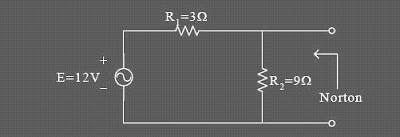
Teorema Norton

Determine the flow norton (IN):
relationship short of the first two series of the string it would look for it, so that the circuit is to be:
Teorema Norton


Resistans R2 will not flow because there is a short relationship. Cash will flow through the short series. Norto Flow (IN) then it is, to be:
Teorema Norton

RN specify:
first remove all sources that are in series, so that the voltage source into a series of short relationship (V= 0). Series is to be:
Teorema Norton

Then combine with the search results Rn and In, of norton String it, can picture the following:
Teorema Norton