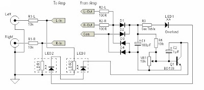
This is a simple peak limiter - performance is quite respectable, and it can be used with conventional amps using bipolar transistors, MOSFETs, valves, etc, as well as BTL (Bridge Tied Load) amplifiers in car audio systems or for hi-fi. It will work with any amplifier from about 10W up to the highest power you are likely to encounter.
The gain control element is a Light Dependent Resistor (LDR). Once this point is reached, a very small increase in amplifier output voltage (and power) will cause the LED to provide much more light, reducing the value of the LDR, and thus reducing the input voltage. The effect is to keep the level more or less constant. This will prevent the amp from clipping (although a small amount on transients is unavoidable), and increase the apparent loudness because the signal is compressed.
The gain control element is a Light Dependent Resistor (LDR). Once this point is reached, a very small increase in amplifier output voltage (and power) will cause the LED to provide much more light, reducing the value of the LDR, and thus reducing the input voltage. The effect is to keep the level more or less constant. This will prevent the amp from clipping (although a small amount on transients is unavoidable), and increase the apparent loudness because the signal is compressed.

The complete assembly must be totally shielded from light. I will leave the exact method to the individual constructor, but you might consider heatshrink tubing, a black 35mm film can, or anything else that comes to hand that is light proof. If metal, it must be earthed along with the shield around the light pipe - make sure that the LED leads are well insulated - a short to earth may damage the amp, and will almost certainly do something unpleasant and / or undesirable.
picture above shows the circuit of the unit. A 10k resistor was selected for the input, and although this is lower than I would like, many power amps have a relatively low input impedance and too much signal would be lost. The LDR simply shunts the signal to earth when it is illuminated. A single unit should control both channels of the power amp as shown. If only one channel is needed, then delete the components for "Right", including the associated light pipe. Use the input circuit shown in Figure 3 to improve limiting by using a higher input resistance.
IMPORTANT- If your amp is operating in bridge mode, the terminal marked "Com" must go to earth - not one or the other of the speaker leads. For automotive use (or any other single supply bridged amplifier), you must use two completely separate circuits, since the speakers operate with a quiescent voltage of about 7V above the chassis (earth) voltage, and there is no usable common terminal available.

The value of R3 must be selected based on the amplifier power. For a 100W amp, a value of 1.8k is about right, but it is likely that a little experimentation will be needed. As a rough guide, the table below will be helpful, and it is probable that the value from the table will be OK. The idea is to limit the current through the LED to a sensible maximum.
The polarity of the connection to the power amp output does not matter since a bridge rectifier is used. Very little current is drawn from the power amp output, and the whole circuit is self limiting, so it is not critical. When complete, advance the volume until you figure that this is a loud as you want the amp to be, and adjust the trimpot until the external LED just flashes. Use a multi-turn trimpot, as the setting is quite touchy. It could be made much less so, but at the expense of circuit flexibility.
Now, if you try to drive the amp harder, the external LED shows that the circuit is working, by flashing brighter, but the volume should remain quite stable. This can be checked with an oscilloscope (ideally), but otherwise just set it by ear. As more signal is driven into the amp, it may sound louder, but this is only because the input signal is being compressed.
Amplifier power in Table 1 for an 8 Ohm load. All diodes are 1N4004 or similar. The voltage rating on the caps should be 63V, and R2-L and R2-R should be rated at at least 1W. VR1 should be a multi-turn trimpot. High brightness LEDs will improve sensitivity and are recommended (but not essential).
Thanks to sound.westhost.com

No comments:
Post a Comment