Showing posts with label Battery. Show all posts

Friday, August 17, 2012

Battery indicator

type='html'>In this part of the investigation in a circuit of battery indicators , this is arise such alarm sound or light up when the battery already weak, so that needs to be replaced or re-charge.


Circuit of Battery indicator


Note:

voltage used is 12 volt
Low voltage warning flow: 15 mA
Alarm tone can be changed with the R7.


Tips Merawat Battery basah
  • Keep the electrolyte in the battery between the lower level and upper level lines. Check it at least once a month.
  • Short of electrolyte will cause sulfation to the elements and reduce the battery's performance in generating electricity flow.
  • Use distilled/demineralized water only for battery filling. Avoid using tap/well/mineral water as they may contain metal ions or organic substances that lower the battery's performance and its life.
  • Clean the battery's surface and keep from any electrolyte spill.
  • Clean the terminal surface using a little grease/lubrication to prevent from oxidation or fungus.
  • Do not connect the positive and negative terminal using a piece of wire as this will damage/terminate the connection between the terminals and elements.
  • Make sure the wire connection to the terminals is tight enough. Loose connection causes sparks, it may cause the battery explodes.
  • Cover the positive terminal's surface using isolator (plastic/rubber) to avoid short circuit to the vehicles body.
  • Cover the battery's surface with plastic/rubber sheet to protect it from dust/dirt blocking the vent holes.
  • Check the vent holes periodically. Blocked vent holes may cause the battery expand and eventually will cause explosion or leakage.


Tips Recharge a battery
Quick-charge recharging.
  • Make sure the charger is at OFF position
  • Attach the clips (red + and black -)
  • Connect the charger to the electricity point
  • Set the timer
  • Set the recharging flow (maximal equivalent to the battery's normal capacity).
  • These steps apply only to an emergency condition.

Normal recharging.
  • Make sure the charger is at OFF position
  • Attach the clips (red + and black -)
  • Connect the battery in parallel fashion
  • The recharge flow is selected for a battery with small capacity
  • Recharge flow volume is 1/10 of normal capacity
  • Recharge time: 3 times constant voltage.

After recharging is completed.
  • Turn off the charger
  • Release the clips on the battery
  • Release the wire from the electricity point.

Friday, August 10, 2012

Rankaian Charge HP Menggunakan battery AA (3 volt)

type='html'>Rankaia Charge hp Menggunakan battery AA (3 volt)
With this tiny thing you can almost charge all the devices which are charged via the USB, like iPod or cellphones, with only two Aa-Cells!

Thus why I should build this?
The reason is completely simple: I am bored empty batteries (IPod, cellphone) while I 'am on the outward journey. And the solution with the linear regulator as 7805 is in fact very
simple, but very unefficient, because: firstly you need a provisioning which provides approximately 3 volts more than you need for the usb and secondly the majority of the cases the difference enters the tension of entry and the tension of output are lost in heat.
The solution to the problem comes from linear technology. Compenent most important of the cicuit presented in the next stages is LT1301 . It is a small stage
to the top of the converter for establishing the mode of commutation actuate the supplys with only some external components.
Rangkaian Charge hp Menggunakan battery AASkema Rangkaian Charge HP Menggunakan battery AA

Rangkaian Charge Spesifikasi:
  • Input: 1,5 to 3 volts
  • Output: 5 Volts @ 200mA max. (really enough to charge an iPod mini or a mobile phone, trust me ;-) )
  • Watts and efficiency:
  • In: 0,95W at 2,5 V
  • Out: 0,875W at 5 V
  • loss: 0,075W
  • 8 percent loss
  • 92% efficiency

The input capacitator should be as close as possible to pin 6 (Vin) of the LT1301!
Keep all cicuit traces short! Directly tie Pin1(GND) Pin8 (PGND) and Pin3 (Shutdown) togheter and connect it to ground. Avoid long soldering times for to prevent destruction of components by overheating... For the detailed placement of the components on the circuit board you can use your own creativity...

So much now its fact, but before connecting it to any device usb, is sure that functions correctly! (the tension should be 5 volts, the LED only would owe rougeoyer, etc) when all ischecked and you are sure that all works you can (if you like it) start to put the hot cast iron around it as a a little protection. If you would put 't as the hot cast iron you can put device in a box of matches or very which you want. left wing of the image you see an older version of the right-sided than you see the smaller and increased version newer


Thursday, August 9, 2012

Lampu Led Emergency|otomatis, Battery 6 volt

type='html'>Lampu led emergency|otomatis dengan battery 6 volt

LED (Light Emitting diode) is used almost in most electronic devices such as television, radio cassette, musical instruments, health equipment, testing devices, automotive, and others, as an indicator or signal light.

LED has many advantages rather than the other, such as: The age of a very long life, a power which is very small (energy), the response of a very fast and good.

In 1999 Philips Lumileds Lighting Company is expected to find a LED that can replace the function of light used for illumination. LED light is out with a very bright white. LUXEON LED is called. R & D office located Lumileds in San Jose and Penang (Malaysia). LUXEON presence makes a variety of new opportunities in applications that require bright light with a compact size.

following is the circuit diagram of a low cost emergency based on white light white LED LED. The provide very bright light which turns on when the mains supply is not there. The circuit has an automatic charger which stops charging when the battery is fully charged

Automatic LED Emergency Light Skema Rangkaian Lampu Led Emergency


The IC LM 317 produces a regulated 7 V for the charging of Battery.Transistor BD 140 drives the out put.Transistor BC 548 and Zener diode controls the charging of the battery.

It is always better to connect a heat sink with BD 140.Before using the circuit out put of LM317 must be set to 7V by adjusting the potentiometer.

Tuesday, August 7, 2012

Rangkaian Charging battery Mobil

type='html'>This is a simple circuit that can be used for charging (mengisi) car battery. In this circuit there is facility for monitoring the charging current and voltage.


Circuit of charging battery Mobil is based on the IC MC78T12ABT . The IC is nothing but a 7812 in TO-3 package with 3A capacity. The transformer T1 steps the mains voltage to 15V AC and diodes D1&D2 does the job of rectification. Capacitor C1 does the filtering and C2 acts as a decoupling capacitor. The ground terminal of IC1 is lifted to 2.1V using the diodes D3 , D4 and D5 . So the output from the IC1 will be a regulated 14.1V (12+2.1). Battery is charged via diode D6. The D6 blocks reverse flow of current from battery to charging circuit when the mains power is not available. Meter M1 shows the charging current and M2 shows the charging voltage.
Charging battery MobilSkema rangkaian charging battery mobil


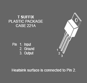
Spesifikasi IC MC78T12ABT

This family of fixed voltage regulators are monolithic integrated circuits capable of driving loads in excess of 3.0 A. These three–terminal regulators employ internal current limiting, thermal shutdown, and safe–area compensation. Devices are available with improved specifications, including a 2% output voltage tolerance, on AC–suffix 5.0, 12 and 15 V device types. Although designed primarily as a fixed voltage regulator, these devices can be used with external components to obtain adjustable voltages and currents. This series of devices can be used with a series–pass transistor to supply up to 15 A at the nominal output voltage.

IC MC78T12ABT
Feature IC MC78T12ABT

• Output Current in Excess of 3.0 A
• Power Dissipation: 25 W
• No External Components Required
• Output Voltage Offered in 2% and 4% Tolerance*
• Thermal Regulation is Specified
• Internal Thermal Overload Protection
• Internal Short Circuit Current Limiting
• Output Transistor Safe–Area Compensation
.

Rangkaian Monitor status battery 12 volt

type='html'>This circuit can be used for monitoring the voltage level of an automobile battery. When battery voltage is 11.5V or less transistor Q1 will be On and LED D1 will be glowing.When battery voltage is between 11.5 - 13.5V, the transistor Q2 will be On and the LED D2 will be glowing.When battery voltage is above 13.5V the transistor Q3 will be On and the LED D3 will be glowing.
Monitor status battery 12 voltSkema rangkaian monitor status battery 12 volt

The battery 12 volt to be monitored can be connected between the terminals A and B and for convenience use LEDs of different colour .

List component of Monitor status battery 12 volt
-R1,R3,R6: 1k 1/4W Resistance
-R2: 100K 1/4W Resistance
-R4,R5,R7,R8: 3.3K 1/4W Resistance
-D1: LED red color
-D2: LED yellow color
-d7: LED green COLOR
-D2,D4,D5,D8,D9: 1N4148 diode 1 ampere
-D6: BZX79C10 diode Zener 10 volt
-D10: BZX79C12 diode Zener 12 volt
-Q1,Q2: BC547 NPN transistor
-Q3: BC557 PNP transistor

Spesifikasi BC547

This device is designed for use as general purpose amplifiers and switches requiring collector currents to 300 mA. Sourced from Process 10. See PN100A for characteristics.
Transistor BC547 (NPN General Purpose Amplifier)

Feature penting Transistor BC547
-(VCEO) Collector-Emitter: Voltage 45 V
-(VCES) Collector-Base Voltage: 50 V
-(VEBO) Emitter-Base Voltage: 6.0 V
-(IC) Collector Current: Continuous 500 mA
-(TJ) Tstg Operating and Storage Junction Temperature Range: -55 to +150 °C

Pengisi Battery Li-On Menggunakan USB

type='html'>USB port it is one of the most useful port. Besides being used as an interface port for the device I / O computer, this port was also used as a filler Li-On Battery (Li-On Battery Charger). Battery charger circuit Li-On can you see in the image below

Pengisi BatterySkema Rangkaian Pengisi Battery Li-On

USB port capable of supplying a maximum voltage 5.25 V with a maximum flow of 0.5 A. Therefore, the above series can only be used to fill a Li-On Battery only. As LM3622 controller IC is used. IC's main function is as decisive end and a battery charging.


IC lm3622 Description

The LM3622 is a charge controller for Lithium-Ion batteries. This monolithic integrated circuit accurately controls an external pass transistor for precision Lithium-Ion battery charging. The LM3622 provides a constant voltage or constant current (CVCC) configuration that changes, as necessary, to optimally charge lithium-ion battery cells. Voltage charging versions (4.1V, 4.2V, 8.2V, and 8.4V) are available for one or two cell battery packs and for coke or graphite anode battery chemistry.

The LM3622 accepts input voltages from 4.5V to 24V. Controller accuracy over temperature is ±30mV/cell for A grade and ±50mV/cell for the standard grade. No precision external resistors are required. Furthermore, the LM3622's proprietary output voltage sensing circuit drains less than 200nA from the battery when the input source is disconnected.

The LM3622 circuitry includes functions for regulating the charge voltage with a temperature compensated bandgap reference and regulating the current with an external sense resistor. The internal bandgap insures excellent controller performance over the operating temperature and input supply range.

The LM3622 can sink 15mA minimum at the EXT pin to drive the base of an external PNP pass transistor. It also has low-voltage battery threshold circuitry that removes this drive when the cell voltage drops below a preset limit. The LVSEL pin programs this threshold voltage to either 2.7V/cell or 2.15V/cell. The low-voltage detection, which is a user enabled feature, provides an output signal that can be used to enable a "wake up charge" source automatically to precondition a deeply discharged pack.

Features IC lm3622
  • Versions for charging of 1 cell (4.1V or 4.2V) or 2 cells (8.2V or 8.4V)
  • Versions for coke or graphite anode
  • Precision (±30mV/cell) end-of-charge control
  • Wide input range: 4.5V-24V
  • Low battery drain leakage: 200nA
  • 15 mA available to drive low cost PNP

Saturday, July 28, 2012

Rangkaian Neon Emergency Light Battery 6 volt

type='html'>Neon Emergency Light Battery 6 volt

This circuit is IC controlled emergency light. This series of automatic switching-on of the light on mains failure and battery charger with overcharge protection. When mains is absent, the relay RL2 is in deenergised state, feeding battery supply to the inverter section via its N / C contacts and switch S1.

rangkaian neon emergency light battery 6 volt
Skema rangkaian neon emergency light battery 6 volt


The inverte
r section comprises IC2 (NE555) which is used in a stable fashion to produce sharp pulses at the rate of 50 Hz for driving the MOSFETs. The output of IC3 is fed to the gate of MOSFET (T4) directly while it is applied to MOSFET (T3) after inversion by gate transistor T2. Thus the power amplifier built around MOSFETs T3 and T4 functions in push-pull mode. The output across the secondary of transformer X2 can easily drive a 230-volt, 20-watt fluorescent tube. In case light is not required to be on during mains failure, simply flip the switch S1 to off position. Battery overcharge preventer circuit is built around IC1 (LM308). Its non-inverting pin is held at a reference voltage of approximately 6.9 volts which is obtained using diode D5 (1N4148) and 6.2-volt zener D6.

The inverting pin of IC1 is connected to the positive terminal of battery. Thus when mains supply is present, Comparator IC1 output is high, unless battery voltage exceeds 6.9 volts. So the transistor T1 is normally forward biased, which energises relay RL1. In this state the battery remains on charge via the N / O contacts of relays RL1 and current limiting resistor R2. When battery voltage exceeds 6.9 volts (overcharged condition), IC1 output goes low and gets deenergised relay RL1, and thus stops further charging of battery. MOSFETs T3 and T4 may be mounted on suitable heat sinks.

Friday, July 13, 2012

Rangkaian Battery Tester ( Penguji Battery)

type='html'>
This circuit can be used to test the battery without the need of power supply or expensive moving-coil voltmeters. It has two Ranges: Pls SW1 is set as shown in the circuit diagram, test the circuit cans 3V to 15V batteries. When SW1 is switched to the other position, only 1.5V cells Can be tested.

Rangkaian Battery Tester ( Penguji Battery)Skema Rangkaian Battery Tester ( Penguji Battery)

List Component:

R1______________2K2 1/4W Resistor
R2______________3R3 1/4W Resistor
R3_____________10R 1/4W Resistor
R4______________4K7 1/4W Resistor
R5_____________33K 1/4W Resistor
R6,R7_________100K 1/4W Resistors
R8____________220K 1/4W Resistor
R9____________330K 1/4W Resistor
R10___________500K Trimmer Cermet
C1,C2__________10nF 63V Polyester Capacitors
C3-C7_________100nF 63V Polyester Capacitors
C8____________220µF 35V Electrolytic Capacitor
D1,D7___________LEDs Red 5mm. (see Notes)
D2-D6________1N4148 75V 150mA Diodes
Q1___________2N3819 General purpose FET
Q2,Q3_________BC337 45V 800mA NPN Transistors
IC1,IC2________7555 or TS555CN CMos Timer ICs
P1_____________SPST Pushbutton
SW1____________DPDT Switch
BUT____________Battery under test

Testing 3V to 15V batteries:
  • Switch SW1 as shown in the circuit diagram.
  • Place the battery under test in a suitable holder or clip it to the circuit.
  • Wait some seconds in order to let C8 reach its full charge.
  • LED D1 illuminates at a constant intensity, independent of battery voltage.
  • If D1 illuminates very weakly or is fully off the battery is unusable.
  • If D1 has a good illumination, press P1 and keep an eye to LED D7. If D7 remains fully off, the battery is in a very good state.
  • If D7 illuminates brightly for a few seconds, the battery is weak. This condition is confirmed by a noticeable weakening of D1 brightness.
  • If D7 illuminates weakly for a few seconds but D1 maintain the same light intensity, the battery is still good but is not new.
Testing 1.5V batteries:
  • Switch SW1 in the position opposite to that shown in the circuit diagram.
  • Place the battery under test in a suitable holder or clip it to the circuit.
  • Wait some seconds in order to let C8 reach its full charge.
  • LED D1 illuminates very weakly only in presence of a new battery, otherwise is off.
  • Press P1 and keep an eye to LED D7. If D7 remains fully off the battery can be in very good state.
  • If D7 illuminates brightly for a few seconds, the battery is weak.
  • If D7 illuminates weakly for a few seconds, the battery is still good but is not new.
  • If you are suspecting a 1.5V cell to be completely discharged, a better test can be made wiring two 1.5V batteries in series, then running the 3V test.

The TS555 is a single CMOS timer which offers very low consumption and high frequency (f(max.) TS555 = 2.7MHz - f(max.) NE555 = 0.1 MHz) Thus, either in Monostable or Astable mode, timing remains very accurate.

IC TS555 PinningIC TS555 Pinning

The TS555 provides reduced supply current spikes during output transitions, which enables the use of lower decoupling capacitors compared to those required by bipolar NE555. Timing capacitors can also be minimized due to high input impedance (1012 W).

Maximum rating ic
Supply Voltage: +18 V
Junction Temperature: +150 oC

Source

Saturday, June 30, 2012

Rangkaian Charge Monitor for 12V battery

type='html'>This circuit project is a function for monitoring the charge level of 12 volt batteries continuously. The circuit possesses two vital features:
  1. reduces the requirement of human attention by about 85%.
  2. highly accurate and sophisticated methods.
A battery is a vital element of any battery-backed system. In many cases the battery is more expensive than the systems it is backing up. We need to Adopt Hence all practical measures to Conserve battery life.

As per manufacturer's data sheets, a 12V rechargeable battery operated Should be within 10. IV and 13.8V. When the battery charges higher than 13.8V it is said to be overcharged, and it discharges below 10.IV Pls Can it be Deeply discharged. A single event of overcharge or deep discharge Can bring down the charge-holding capacity of a battery by 15 to 20%.

Rangkaian charge monitor for 12V batterySkema rangkaian charge monitor for 12V battery

Note:

For calibrating the upper and lower reference levels, a digital multimeter and a variable regulated power supply source are required. For calibrating the lower reference voltage, follow the steps given below:
  • Set the output of power supply source to 10. IV.
  • Connect the power supply source in place of the battery.
  • Now the display will show some reading. At this point vary preset VR2 until the reading on the display just changes from 1 to 0.
  • The higher reference voltage is calibrated similarly by setting the power supply to 13.8V and varying preset VR1 until reading on the display just changes from 8 to 9.


How to Work a Circuit of Charge Monitor for 12V Battery

Input from the battery under test is applied to LM3914 1C. This applied voltage is ranked anywhere between 0 and 10, depending upon its magnitude. The lower reference voltage of 10.IV is ranked '0' and the upper voltage of 13.8V is ranked as '10.' (Outputs 9 and 10 are logically ORed in this circuit.) This calibration of reference voltages is explained above.

1C 74LS147 is a decimal-to-BCD priority encoder which converts the output of LM3914 into its BCD complement. The true BCD is obtained by using the hex inverter 74LS04. This BCD output is displayed as a decimal digit after con version using IC5 (74LS247), which is a BCD-to-seven-segment decoder/driver. The seven-segment LED display (LTS-542) is used because it is easy to read compared to a bar graph or, for that matter, an analogue meter. The charge status of the battery can be quickly calculated from the display. For instance, if the display shows 4, it means that the battery is charged to 40 per cent of its maximum value of 13.8V.

The use of digital principles enables us to employ a buzzer that sounds whenever there is an overcharge or deep discharge, or there is a need to conserve battery charge. A buzzer is wired in the circuit such that it sounds whenever battery-charge falls to ten per cent. At this point it is recommended that unnecessary load be switched off and the remaining charge be conserved for more important purposes.

Another simple combinational logic circuit can also be designed that will sound the buzzer when the display shows 9. Further charging should be stopped at this point in order to pre vent overcharge.

Friday, June 29, 2012

Mobile Phone Battery Charger Circuit

type='html'>
This Mobile phone chargers circuit presented here comes as a low-cost alternative to charge mobile telephones/battery packs.

Mobile Phone Battery Charger CircuitCircuit of Mobile Phone Battery Charger

The 220V AC mains supply is downconverted to 9V AC by transformer X1. The transformer output is rectified by diodes D1 through D4 wired in bridge configuration and the positive DC supply is directly connected to the charger’s output contact, while the negative terminal is connected through current limiting resistor R2. LED2 works as a power indicator with resistor R1 serving as the current limiter and LED3 indicates the charging status. During the charging period, about 3 volts drop occurs across resistor R2, which turns on LED3 through resistor R3. An external 12V DC supply sourcecan also be used to energise the charger, where resistor R4, after polarity protection diode D5, limits the input current to a safe value. The 3-terminal positive voltage regulator LM7806 (IC1) provides a constant voltage output of 7.8V DC since LED1 connected between the common terminal (pin 2) and ground rail of IC1 raises the output voltage to 7.8V DC. LED1 also serves as a power indicator for the external DC supply. After constructing the circuit on a veroboard, enclose it in a suitable cabinet. A small heat sink is recommended for IC1.

Circuit Design By: PRINCE PHILLIPS
Source: www.electronicsforu.com

Thursday, June 28, 2012

LTC4060 - NiMH/NiCd Battery Charger Circuit

type='html'>
This cheap and easy to build NiCd/NiMH Battery Charger circuit is suitable for automatically charging a wide range of batteries for many applications. This 'intelligent' charger was designed for high current and rapid charge applications such as cordless power tools and model racing cars. These battery packs are expensive and sometimes difficult to purchase. This charger uses the cell manufacturer's recommended charge method, to safely and quickly charge batteries.
Rangkaian NiMH/NiCd Battery ChargerSkema Rangkaian NiMH/NiCd Battery Charger

Linear Technology Corporation introduces the LTC4060, an autonomous 1- to 4-cell, 0.4A to 2A linear NiMH and NiCd battery charger. The LTC4060 includes all the functions required for a battery charger circuit. The design is simple and needs only three passive components. The LTC4060 also eliminates the need for a sense resistor and blocking diode, which increases efficiency and lowers the solution cost. This IC is targeted at applications including portable medical equipment, automotive diagnostic systems and industrial/telecom test devices.

The LTC4060 - NiMH/NiCd Battery Charger circuit Features
  • Complete Fast Charger Controller for Single, 2-, 3- or 4-Series Cell NiMH/NiCd Batteries
  • No Firmware or Microcontroller Required
  • Termination by –∆V, Maximum Voltage or Maximum Time
  • No Sense Resistor or Blocking Diode Required
  • Automatic Recharge Keeps Batteries Charged
  • Programmable Fast Charge Current: 0.4A to 2A
  • Accurate Charge Current: ±5% at 2A
  • Fast Charge Current Programmable Beyond 2A with External Sense Resistor
  • Automatic Detection of Battery
  • Precharge for Heavily Discharged Batteries
  • Optional Temperature Qualified Charging
  • Charge and AC Present Status Outputs Can Drive LED
  • Automatic Sleep Mode with Input Supply Removal
  • Negligible Battery Drain in Sleep Mode: <>
  • Manual Shutdown
  • Input Supply Range: 4.5V to 10V
  • Available in 16-Lead DFN and TSSOP Packages