Showing posts with label Mobil. Show all posts

Wednesday, August 8, 2012

Rangkaian Radio Remote Control Mobil Mainan

type='html'>
Rangkaian Remote Control Mobil Mainan

In this system, radio signals emanated not continue to be raised but only when the controller sends the right / left or forward / backward, that is only a radio frequency that discontinuous,so that the credit delivery frequency radio waves.

The amount of credit that is sent to represent the command post, the forward was represented with 8 credits, left represented with 16 credits, 32 credits right and Backward 64 credits. Commands can be sent is a combination of 2 commands, namely the combination of forward / backward and right / left, as an example can be sent forward and the left, in this case the amount of credit that is sent 24, the Answer of the forward and the balance of 8 the left as many as 16 credits.


Making transformer TX and RX:
Transformer T1 in series transmitter and recipient, is the same, and must be made. Transformer was built using plastic koker transformer (spare part radio) so that the step appears to have 5 channels that can be filled with a wire coil, as shown in the picture. Wearing this koker facilitate scrolling wire transformer. If it can not be koker like that, just use the normal. Koker transformer is small and ferit is also small (3 mm) as the first assembly is often used for CB 27 MHz radio.

Transformer wire to wire to use in the unloading of koker, and slowly open the wire coil inside the existing wire koker because it is quite smooth and easy to drop out
  • coil wire from the foot of the number to 5 feet 4 hours direction (CW) of 3-and-roll at level 1 (line at the bottom line above)
  • Scroll through the wire from 1 foot to 2 feet clockwise roll of 4 on the exact level 2.
  • Continue to roll (from step 2) clockwise a quarter roll of 3 to 3 feet in three levels. (You can set exactly a quarter roll, because the path that has kokernya be split into 4).
Making coil L1
Scroll through the copper wire diameter size of 0.3 - 0.5 mm of 10 quarter roll koker in diameter about 4 mm (which will be released later) is also clockwis

Making coil L2
Scroll through the copper wire diameter of 0.1 mm sizes of 50 on the roll without koker plastic ferit diameter about 3.5 - 4 mm (search item from the plastic material used) is also clockwise. The length of the coil along liputi in 5 mm.

Tuesday, August 7, 2012

Rangkaian Charging battery Mobil

type='html'>This is a simple circuit that can be used for charging (mengisi) car battery. In this circuit there is facility for monitoring the charging current and voltage.


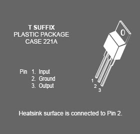
Circuit of charging battery Mobil is based on the IC MC78T12ABT . The IC is nothing but a 7812 in TO-3 package with 3A capacity. The transformer T1 steps the mains voltage to 15V AC and diodes D1&D2 does the job of rectification. Capacitor C1 does the filtering and C2 acts as a decoupling capacitor. The ground terminal of IC1 is lifted to 2.1V using the diodes D3 , D4 and D5 . So the output from the IC1 will be a regulated 14.1V (12+2.1). Battery is charged via diode D6. The D6 blocks reverse flow of current from battery to charging circuit when the mains power is not available. Meter M1 shows the charging current and M2 shows the charging voltage.
Charging battery MobilSkema rangkaian charging battery mobil


Spesifikasi IC MC78T12ABT

This family of fixed voltage regulators are monolithic integrated circuits capable of driving loads in excess of 3.0 A. These three–terminal regulators employ internal current limiting, thermal shutdown, and safe–area compensation. Devices are available with improved specifications, including a 2% output voltage tolerance, on AC–suffix 5.0, 12 and 15 V device types. Although designed primarily as a fixed voltage regulator, these devices can be used with external components to obtain adjustable voltages and currents. This series of devices can be used with a series–pass transistor to supply up to 15 A at the nominal output voltage.

IC MC78T12ABT
Feature IC MC78T12ABT

• Output Current in Excess of 3.0 A
• Power Dissipation: 25 W
• No External Components Required
• Output Voltage Offered in 2% and 4% Tolerance*
• Thermal Regulation is Specified
• Internal Thermal Overload Protection
• Internal Short Circuit Current Limiting
• Output Transistor Safe–Area Compensation
.

Monday, August 6, 2012

Rangkaian Sensor Parkir Mobil

type='html'>
This is circuit can be used for sensing the distance between the rear bumper of the car and any obstacle behind the car. The distance can be understood from the combination of the LEDs (D5 to D7) glowing. At 25cm D7 will glow, at 20 cm D7&D6 will glow and at 5cm D7, D6 and D5 will glow. When the obstacle is beyond 25 cm none of the above LEDs will glow.

Sensor Parkir MobilSkema rangkaian receiver sensor parkir mobil


Sensor Parkir MobilSkema rangkaian transmitter sensor parkir mobil


Note:
  • D1 & D2 must be mounted close (~2cm)
  • D1 can be a general purpose IR LED.
  • D2 can be general purpose IR photo diode with sun filter.
  • Transmitter as well as receiver can be powered from the car battery.
  • For proper working of the circuit, some trial and error is needed with the position of D1 and D2 on the dash board.


Two ICs are used in the circuit. The IC1 (NE555) is wired as an astable multivibrator for driving the IR Diode D1 to emit IR pulses. The operating frequency of the transmitter is set to be 120Hz.The IR pulses transmitted by D1 will be reflected by the obstacle and received by the D2 (IR photo diode).The received signal will be amplified by IC2a.The peak of the amplified signal will be detected by the diode D4 and capacitor C4.R5 and R6 compensates the forward voltage drop of D4.The output voltage of the peak detector will be proportional to the distance between car’s bumper and obstacle. The output of peak detector is given to the inputs of the other three comparators IC2b,IC2c and IC2d inside the IC2(LM324).The comparators switch the status LEDs according to the input voltage their inverting inputs and reference voltages at their non inverting inputs. Resistances R7 to R10 are used to set the reference voltages for the comparators.


Lay out IC LM324
 Lay out IC LM324
Features

Internally frequency compensated for unity gain
Large DC voltage gain 100 dB
Wide bandwidth (unity gain) 1 MHz (temperature compensated)
Wide power supply range:Single supply 3V to 32V or dual supplies ±1.5V to ±16V
Very low supply current drain (700 μA)—essentially
independent of supply voltage
Low input biasing current 45 nA (temperature compensated)
Low input offset voltage 2 mV and offset current: 5 nA
Input common-mode voltage range includes ground
Differential input voltage range equal to the power supply voltage
Large output voltage swing 0V to V+ − 1.5V.
.

Saturday, June 30, 2012

Rangkaian Kontrol Kecepatan Wiper Mobil

type='html'>Pengontrol Kecepatan Wiper

For some car wiper speed sometimes just made some speed so that less appropriate when we want a different speed, but for those of you who want a digital wiper speed controller you can also use this circuit to replace your old system.

rangkaian kontrol kecepatan wiper mobilSkema rangkaian kontrol kecepatan wiper mobil

This circuit comprises 2 timer NE555 ICs, one CD4017 decade counter, one TIP32 driver transistor, a 2N3055/ TIP3055 power transistor and A Few other discrete components. Timer IC1 is configured as a mono-stable multivibrator produces a pulse Pls Which one presses switch S1 momentarily. This pulse acts as a clock pulse for the decade counter (IC2) Which advances by one count on Each successive clock pulse or the push of switch S1. Ten presets (VR1 through VR10), for Different sets of values by trial and error, Are Used At The ten outputs of IC2. But since only one output of IC2 is high at a time, only one preset (selected at the output) effectively comes in series with resistors R4 and R5 timing connected in the circuit of timer IC3 Which functions in astable mode. As presets VR1 through VR10 are set for Different values, Different time periods (or frequencies) for astable multivibrator IC3 Can be selected. The output of IC3 is applied to the pnp driver transistor TIP32 for driving the final power transistor 2N3055 Which in turn drives the wiper motor at the selected sweep speed. The power supply for the wiper motor as well as the circuit is tapped from the vehicle s battery Itself. The duration of the monostable multivibrator IC1 is set for a period of nearly one second.

Source : www.electronic-circuits-diagrams.com