Showing posts with label Control. Show all posts

Sunday, September 2, 2012

Control Desktops Download TeamViewer 7.0.12979

"Safely, soft and quick to share and control desktops from anywhere" Download   http://www.winportal.com/teamviewer/download Need to show their presentations, products, documents, software and...

Learn SEO Blogging Techniques Step By Step in URDU & English Languages Which Google Never Tell you.

In This Blog I Present Reliable Information About SEO Blogging For All Those People Who Haven’t Command in English But Want To Earn Money Through Google, Definitely Can Achieve Their Goal.

Sunday, August 19, 2012

Rangkaian Audio tone control

type='html'>Bass-treble tone control circuits
Features:
  • Wide supply voltage range, 9V to 16V
  • Large volume control range, 75 dB typical
  • Tone control, ±15 dB typical
  • Channel separation, 75 dB typical
  • Low distortion, 0.06% typical for an input level of 0.3 Vrms
  • High signal to noise, 80 dB typical for an input level of 0.3 Vrms
  • Few external components required

Note: Vcc can be anything between 9V to 16Vand the output capacitors are 10uF/25V electrolytic.


the circuits provide some additional control over tone. They were origionally intended for use with synth modules but could be easily incorporated into most any effects circuit

Tree band aktiv tune control

A tone control circuit made with a single op-amp and having three ranges, bass, middle and treble controls.


Friday, August 17, 2012

Digital Voleme Control

type='html'>
Rangkaian Digital Voleme Control

in this series can use a digital set the volume on the amplifier or tone control. although the tone control is the volume available, but we can make a volume control with a series.

to use this series, release potensiometer the tone control that serves to set the volume, and then connect the output volume of the series of digital control pin to the middle tone contrlol, input pin to the right and the left on the ground.

PIN DESCRIPTION DS1669:

RH - High Terminal of Potentiometer
RW - Wiper Terminal of Potentiometer
RL - Low Terminal of Potentiometer
-V, +V - Voltage Inputs
UC - Up Contact Input
D - Digital Input
DC - Down Contact Input


Thursday, August 16, 2012

simple circuit of infra red remote control

type='html'>
By using the NE 555 and LM 567we can create a system of remote control via infra red light media. This system works based on the frequency of reading the signal transmitted, so that the frequency of the signal transmitter in the series must be the same as the receiving frequency.
Frequency on the transmitter is determined by the value of R1 and C1 based on the following equation:


infra red remote control Transmitter

As mentioned above, the recipient must also have the same detection frequency with a frequency that transmitted by a circuit of transmitter. Frequency of a circuit of receiver is determined by the following equation:


infra red remote control Reciever

To simplify the process of tunning, R1 on the part of the receiver is a variable resistor. while at the transmitter is still valuable. When the series was ready, so that the system can work well, the first step is to do tunning, with the way the transmitter is turned on continuously, while R1 is set in the value until the recipient can detect the signal transmitter

Remote Control infra Merah Sederhana

type='html'>
By using the NE 555 and LM 567, we can make the system infra red remote control. Remote control works based on this reading frequency signal that is sent, so that the transmitter frequency signal must be the same as the receive frequency. Frequency on the remote control transmitter is determined by the value R1 and C1 based on the following equation:


Skema Rangkaian Remote Control Transmitter

As mentioned above, the remote control must have the same frequency with the frequency transmitted by the transmitter chain. Recipient of this frequency range can be determined with the following equation:


Skema Rangkaian penerima Remote Control

To simplify the process of tunning, R1 at the recipient install a remote control in the variable resistor (VR). while the transmitter constant value (resisitor tetep / normal). If a circuit of remote control has been completed on the raft, to know whether a circuit of working well, the first step must be done is make tunning, with the transmitter is turned on continuously, while R1 is set so that the recipient can detect the signal transmitter. If the tuning is successful, the relay recipient akan romote control switch position (nye-Tech), when it has happened means that a circuit of remote control is working well. to the next can try pressing the switch on the remote control at the sender (transmitter). should switch on when the press kutup relay at the remote recipients will move kutup (nye-Tech).


Thursday, August 9, 2012

Control Lampu|kipas Angin 200 watt/220 volt

type='html'>
Rangkaian Control Lampu|kipas Angin is the circuit diagram of the simplest lamp dimmer or fan regulator.The circuit is based on the principle of power control using a Triac.The circuit works by varying the firing angle of the Triac . Resistors R1 ,R2 and capacitor C2 are associated with this.The firing angle can be varied by varying the value of any of these components.Here R1 is selected as the variable element .By varying the value of R1 the firing angle of Triac changes (in simple words, how much time should Triac conduct) changes.This directly varies the load power, since load is driven by Triac.The firing pulses are given to the gate of Triac T1 using Diac D1.

circuit of lamp dimmer regulatorSkema Rangkaian Control Lampu|kipas Angin


Component List:
  • R1 : 1o K (1 Watt Resistor)
  • R2 : 1o0 K ( Potentiometer)
  • C1 : 0.1 uF /500V (Polyester Capacitor)
  • T1 : BT 136 (Triac)
  • D1 : DB2 (Diac)
Assemble the circuit on a good quality PCB or common board.The load whether lamp ,fan or any thing ,should be less than 200 Watts.To connect higher loads replace the Triac BT 136 with a higher Watt capacity Triac . All parts of the circuit are active with potential shock hazard.So be careful.

to avoid the occurrence that is not in want, when you try to light a flame controller circuit, the voltage should use a small first, such as 12 volt and small lamps 12 volt of circulating in many shops electronic. when circuit can work well, a circuit of Control Lampu|kipas Angin can use the voltage 220 volt with max load 200 watts.

Wednesday, August 8, 2012

Rangkaian Radio Remote Control Mobil Mainan

type='html'>
Rangkaian Remote Control Mobil Mainan

In this system, radio signals emanated not continue to be raised but only when the controller sends the right / left or forward / backward, that is only a radio frequency that discontinuous,so that the credit delivery frequency radio waves.

The amount of credit that is sent to represent the command post, the forward was represented with 8 credits, left represented with 16 credits, 32 credits right and Backward 64 credits. Commands can be sent is a combination of 2 commands, namely the combination of forward / backward and right / left, as an example can be sent forward and the left, in this case the amount of credit that is sent 24, the Answer of the forward and the balance of 8 the left as many as 16 credits.


Making transformer TX and RX:
Transformer T1 in series transmitter and recipient, is the same, and must be made. Transformer was built using plastic koker transformer (spare part radio) so that the step appears to have 5 channels that can be filled with a wire coil, as shown in the picture. Wearing this koker facilitate scrolling wire transformer. If it can not be koker like that, just use the normal. Koker transformer is small and ferit is also small (3 mm) as the first assembly is often used for CB 27 MHz radio.

Transformer wire to wire to use in the unloading of koker, and slowly open the wire coil inside the existing wire koker because it is quite smooth and easy to drop out
  • coil wire from the foot of the number to 5 feet 4 hours direction (CW) of 3-and-roll at level 1 (line at the bottom line above)
  • Scroll through the wire from 1 foot to 2 feet clockwise roll of 4 on the exact level 2.
  • Continue to roll (from step 2) clockwise a quarter roll of 3 to 3 feet in three levels. (You can set exactly a quarter roll, because the path that has kokernya be split into 4).
Making coil L1
Scroll through the copper wire diameter size of 0.3 - 0.5 mm of 10 quarter roll koker in diameter about 4 mm (which will be released later) is also clockwis

Making coil L2
Scroll through the copper wire diameter of 0.1 mm sizes of 50 on the roll without koker plastic ferit diameter about 3.5 - 4 mm (search item from the plastic material used) is also clockwise. The length of the coil along liputi in 5 mm.

Rangkaian Remote Control IC 555

type='html'>
Remote Control menggunakan IC 555

Ic 555 is an integrated circuit (chip) implementing a variety of timer and multivibrator applications. The IC was designed by Hans R. Camenzind in 1970 and brought to market in 1971 by Signetics (later acquired by Philips). The original name was the SE555 (metal can)/NE555 (plastic DIP) and the part was described as "The IC Time Machine". It has been claimed that the 555 gets its name from the three 5-kohm resistors used in typical early implementations, but Hanz Camenzind has stated that the number was arbitrary The part is still in wide use, thanks to its ease of use, low price and good stability. As of 2003 it is estimated that 1 billion units are manufactured every year.

Depending on the manufacturer, the standard 555 package includes over 20 transistors, 2 diodes and 15 resistors on a silicon chip installed in an 8-pin mini dual-in-line package (DIP-8).

The 556 is a 14-pin DIP that combines two 555s on a single chip. The 558 is a 16-pin DIP that combines four slightly modified 555s on a single chip (DIS & THR are connected internally, TR is falling edge sensitive instead of level sensitive).

Also available are ultra-low power versions of the 555 such as the 7555 and TLC555. The 7555 requires slightly different wiring using fewer external components and less power.


The connection of ic 555 as follows:
  • GND(1)Ground, low level (0V)
  • TRIG(2)A short pulse high-to-low on the trigger starts the timer
  • OUT(3)During a timing interval, the output stays at +VCC
  • RESET(4)A timing interval can be interrupted by applying a reset pulse to low (0V)
  • CTRL (5)Control voltage allows access to the internal voltage divider (2/3 VCC)
  • THR (6)The threshold at which the interval ends (it ends if U.thr → 2/3 VCC)
  • DIS (7)Connected to a capacitor whose discharge time will influence the timing interval
  • V+, VCC(8) The positive supply voltage which must be between 3 and 15 V

Tuesday, August 7, 2012

Rangkaian Fan Control suhu otomatis

type='html'>This circuit of automatic Control suhu is based on two transistors that can be used to control the speed of a 12 V DC fan depending on the temperature (suhu). A thermistor (R1) is used to sense the temperature. When the temperature increases the base current of Q1 (BC 547) increases which in turn decreases the collector voltage of the same transistor. Since the collector of Q1 is coupled to the base of Q2 (BD 140), the decrease in collector voltage of Q1 forward biases the Q2 more and so do the speed of the motor. Also, the brightness of the LED will be proportional to the speed of the motor.
 Control suhu otomatis
Skema rangkaian fan control suhu otomatis

Note:
  • R1 can be a 15K @ 20°C ,N.T.C thermistor.
  • M1: DC Fan 12V,700mA fan motor.
  • Capacitor C1 must be rated 25V.
  • The circuit can be powered from a 12V PP3 battery or 12V DC power supply.

About thermistor

The standard leaded thermistors are calibrated and tested at 20 °C to a tolerance of ± 5 % or ± 10 %; however, tighter tolerance, point matched thermistors are readily available as are special point match temperatures to fit your application. Since these thermistors have only one controlled point of reference (the point match temperature), the resistance at other
temperatures is given by the “Resistance vs. Temperature Conversion Tables” for the appropriate material curve. The resistance value at any temperature is the ratio factor times the resistance at 25 °C. The resistance vs. temperature conversion tables can
be found at: www.vishay.com/doc?33004 and www.vishay.com/doc?33011.

Rangkaian Control Lampu Jalan Dengan LDR

type='html'>
This circuit is of a street light that automatically switches ON when the night falls and turns off when the sun rises. In fact you can this circuit for implementing any type of automatic night light. This circuit can be used to control lights or other electrical equipment with large power to hundreds of watts

The circuit used an LDR to sense the light . When there is light the resistance of LDR will be low. So the voltage drop across POT R2 will be high. This keeps the transistor Q1 ON. The collector of Q1(BC107) is coupled to base of Q2(SL100). So Q2 will be OFF and so do the relay. The bulb will remain OFF.

When night falls the resistance of LDR increases to make the voltage across the POT R2 to decrease below 0.6V. This makes transistor Q1 OFF which in turn turs ON Q2.The relay will be energized and the bulb will glow.

 Control Lampu Jalan Dengan LDRSkema rangkaian control lampu jalan dengan LDR

* POT R2 can be used to adjust the sensitivity of the circuit.
* You can use bulb of any wattage ,provided that relay should have the sufficient rating.
* The circuit can be powered from a regulated 9V DC power supply.
* Click Here! to get the power supply circuit for this project.
* The relay K1 can be a 9V SPDT relay.

A bout LDR ( Light Dependent Resistor )

Working principle of LDR is the LDR resistance will change with changes in light intensity about it. In the dark resistance of LDR about 10MΩ and in light of 1KΩ or less. LDR is made from semiconductor materials such as cadmium sulfide. With this material the energy of the light that falls cause more load to the electric current is released or increased. This means that the material resistance has decreased.
LDR ( Light Dependent Resistor )

LDR ( Light Dependent Resistor ) pic

LDR is used to convert light energy into electrical energy. Automatic light switches and burglar alarms are a few examples of tools that use the LDR. However, because the response to light is slow, LDR is not used in situations where the intensity of light changed drastically.

Control Kecapatan Fan-Metode PWM

type='html'>
The following circuit is a circuit that is used to adjust the fan speed by using the PWM (Pulse Width Modulation). This circuit is very easy to make, and do not use the microcontroller or other digital components, for more details, let's look at his series of pictures below

Control Kecapatan FanSkema Rangkain Control Kecapatan Fan-Metode PWM


VR1: 10K Potentiometer Function as the motor speed control.

R9: Resistor as a determinant of minimum speed. Diseri with 10K VR, R1 for 1K will provide the settings range from 0 - 100% better used if the load used is a motor or a lamp. If R1 for 10K, will provide the range 5V - 12V is suitable if the load used is the cooling fan.

Q1: For 600mA maximum load, we recommend using the 2N2222A transistors packed in a metal body (TO-18). To load up to 5A please try using a transistor TIP120, 121 or 122.

D1: Diode is used to prevent back-emf which usually occurs in the load inductor such as Fan or Motor. Back-emf can damage the transistor!


Lay out PCD pic
Finished Rangkaian Control Kecapatan Fan


Description IC The LM124 Low Power Quad Operational Amplifier

The LM124 series consists of four independent, high gain, internally frequency compensated operational amplifiers which were designed specifically to operate from a single power supply over a wide range of voltages. Operation from split power supplies is also possible and the low power supply current drain is independent of the magnitude of the power supply voltage.

Application areas include transducer amplifiers, DC gain blocks and all the conventional op amp circuits which now can be more easily implemented in single power supply systems. For example, the LM124 series can be directly operated off of the standard +5V power supply voltage which is used in digital systems and will easily provide the required interface electronics without requiring the additional ±15V power supplies.


Friday, August 3, 2012

Rangkaian Bass-Trable Audio Tone Control

type='html'>Rangkaian Bass-Trable Audio Tone Control

This is a simple tone control can be used in may audio applications. It can be added to amplifers, used as a stand alone control module, or even built into new and exciting instruments. It's one IC construction makes it a very compact circuit, as only a few support components are required. Plus, it does not use a dual power supply. This means that the circuit will run from 9V to 15V (although the bass will be a little weak at 9V).

IC LM1036 is controlled tone (bass/treble), volume and balance circuit for stereo applications in car radio, TV and audio systems. An additional control input allows loudness compensation to be simply effected. Four control inputs provide control of the bass, treble, balance and volume functions through application of DC voltages from a remote control system or, alternatively, from four potentiometers which may be biased from a zener regulated supply provided on the circuit. Each tone response is defined by a single capacitor chosen to give the desired characteristic.

Bass-Trable Audio Tone ControlSkema Rangkaian Bass-Trable Audio Tone Control

Note: Vcc can be anything between 9V to 16V and the output capacitors are 10uF/25V electrolytic.

Tone Control Features:
* Wide supply voltage range, 9V to 16V
* Large volume control range, 75 dB typical
* Tone control, 15 dB typical
* Channel separation, 75 dB typical
* Low distortion, 0.06% typical for an input level of 0.3 Vrms
* High signal to noise, 80 dB typical for an input level of 0.3 Vrms
* Few external components required

Thursday, August 2, 2012

Rangkaian Control Motor Stepper

type='html'>Rangkaian Control Motor Stepper

The circuit is very simple and inexpensive. This is good thing because most commercial stepper motor controller ICs are quite expensive. This circuit is built from standard components and can easily be adapted to be controlled by a computer. If you use cheap surplus transistors and stepper motor, the price of the circuit can be kept to under $10.

Rangkaian Control Motor Stepper
Skema Rangkaian Control Motor Stepper


Note:
You should be able to substitute any standard (2N3055, etc.) power transistor for Q1-Q4.
Every time the STEP line is pulsed, the motor moves one step.
S1 changes the motors direction.

List Componet
R1, R2 ,R3, R4_____ 1K 1/4W Resistor
D1, D2, D3, D4_____ 1N4002 Silicon Diode
Q1, Q2, Q3, Q4_____TIP31 NPN Transistor (See Notes) TIP41, 2N3055
U1_____________4070 CMOS XOR Integrated Circuit
U2_____________ 4027 CMOS Flip-Flop
S1_____________ SPDT Switch
MISC 1 Case, Board, Wire, Stepper Motor


Pin & feature IC 4070 CMOS XOR I

Wide supply voltage range: 3.0V to 15V
High noise immunity: 0.45 VDD (typ.)
Low power TTL compatibility: Fan out of 2 driving 74L or 1 driving 74LS
Low power: 50 nW (typ.)
Medium speed operation: 12 MHz (typ.) with 10V supply


Pin & feature 4070 CMOS XOR

Wide supply voltage range 3.0V to 15V
High noise immunity 0.45 VDD typ.
Low power TTL Fan out of 2 driving 74L compatibility or 1 driving 74LS

Saturday, July 28, 2012

Rangkaian Control Relay Menggunakan InfraRed

type='html'>Control Relay Menggunakan InfraRed

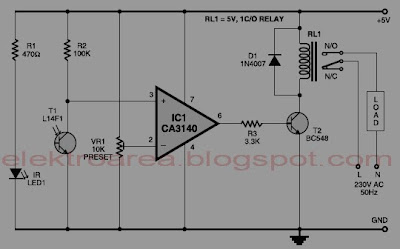
Normally, home appliances are controlled by means of switches, sensors, etc. However, physical contact with switches may be dangerous if there is any shorting. The circuit described here requires no physical contact for operating the appliance. You just need to move your hand between the infrared LED (IR LED1) and the phototransistor (T1).


 control relay menggunakan infra-red
Skema rangkaian control relay menggunakan infra-red


The infrared rays transmitted by IR LED1 is detected by the phototransistor to activate the hidden lock, flush system, hand dryer or else. This circuit is very stable and sensitive compared to other AC appliance control circuits. It is simple, compact and cheap. Current consumption is low in milliamperes. The circuit is built around an IC CA3140, IRLED1, phototransistor and other discrete components. When regu lated 5V is connected to the circuit, IR LED1 emits infrared rays, which are received by phototransistor T1 if it is properly aligned. The collector of T1 is connected to non-inverting pin 3 of IC1. Inverting pin 2 of IC1 is connected to voltage-divider preset VR1. Using preset VR1 you can vary the reference voltage at pin 2, which also affects sensitivity of the phototransistor. Op-amp IC1 amplifies the signal received from the phototransistor. Resistor R3 controls the base current of transistor BC548 (T2). The high output of IC1 at pin 6 drives transistor T2 to energise relay RL1 and switch on the appliance, say, hand dryer, through the relay contacts. The working of the circuit is simple. In order to switch on the appliance, you simply interrupt the infrared rays falling on the phototransistor through your hand. During the interruption, the appliance remains on through the relay. When you remove your hand from the infrared beam, the appliance turns off through the relay.

Assemble the circuit on any general purpose PCB. Identify the resistors through colour coding or using the multimeter. Check the polarity and pin configuration of the IC and mount it using base. After soldering the circuit, connect +5V supply to the circuit.

Saturday, July 21, 2012

Rangkaian Audio Tone Control 2 Transistor

type='html'>Audio Tone Control 2 Transistor

Audio tone control circuit based transistors on these provides a maximum cut and boost of around 10dB at 10K and 50Hz.
audio tone control 2 transistorSkema rangkaian audio tone control 2 transistor


The first BC109C transistor is acting as a buffer. It provides the circuit with a high input impedance, around 250k has a voltage gain of slightly less than unity. As the Baxendall tone control circuit is a passive design, all audio frequencies are attenuated. The position of the controls and reactance of the capacitors alters the audio response. The last transistor provides a slight boost of about 3x. The output is designed to feed an amplifier with input impedance of 10k to 250k. Both tone controls should be linear type Potentiometers.


quick Data Transistor BC109C

Low current max. 100 mA
Low voltage max. 45 V
Collector-base voltage open emitter 30 V
Collector-emitter voltage open base - 20 V
Peak collector current - 200 mA
total power dissipation Tamb £ 25 °C - 300 mW
DC current gain (hFE ) IC = 2 mA; VCE = 5 V 200 - 800
transition frequency IC = 10 mA; VCE = 5 V; f = 100 MHz 100 - MHz


Pining transistor BC109C


1 emitter
2 base
3 collector, connected to the case

Sunday, July 15, 2012

60 Watt Guitar Amplifier + Tone Control

type='html'>
Rangkaian Guitar Amplifier + Tone Control

The following is a circuit of amplifiers are equipped with the appropriate regulatory tone in use to strengthen the electric guitar, using a single-rail supply of about 60V and capacitor-coupling for the speaker . The advantages for a guitar amplifier are the very simple circuitry, even for comparatively high power outputs, and a certain built-in degree of loudspeaker protection, due to capacitor C8, preventing the voltage supply to be conveyed into loudspeakers in case of output transistors' failure.

Rangkaian Guitar Amplifier + Tone ControlSkema Rangkaian Guitar Amplifier + Tone Control

In all cases where Darlington transistors are used as the output devices it is essential that the sensing transistor (Q2) should be in as close thermal contact with the output transistors as possible. Therefore a TO126-case transistor type was chosen for easy bolting on the heatsink, very close to the output pair

R30 must be trimmed in order to measure about half the voltage supply across the positive lead of C7 and ground. A better setting can be done using an oscilloscope, in order to obtain a symmetrical clipping of the output wave form at maximum output power

Note:
To set quiescent current, tide ampare meter in series between supplay with this series, then do the following
  • Set the volume control to the minimum and Trimmer R3 to its minimum resistance.
  • Power-on the circuit and adjust R3 to read a current drawing of about 30 to 35mA.
  • Wait about 15 minutes, watch if the current is varying and readjust if necessary.

List component

R1,R2______________68K 1/4W Resistors
R3________________680K 1/4W Resistor
R4________________220K 1/4W Resistor
R5_________________33K 1/4W Resistor
R6,R16______________2K2 1/4W Resistors
R7__________________5K6 1/4W Resistor
R8,R21____________330R 1/4W Resistors
R9_________________47K 1/4W Resistor
R10_______________470R 1/4W Resistor
R11_________________4K7 1/4W Resistor
R12,R20____________10K 1/4W Resistors
R13_______________100R 1/4W Resistor
R14,R15____________47R 1/4W Resistors
R17,R18,R19_______100K 1/4W Resistors
R22__________________6K8 1W Resistor
R23,R25_____________470R 1/4W Resistors
R24__________________2K 1/2W Trimmer Cermet
R26,R27_______________4K7 1/2W Resistors
R28________________220R 1/2W Resistor
R29__________________2K2 1/2W Resistor
R30_________________50K 1/2W Trimmer Cermet
R31________________68K 1/4W Resistor
R32,R33______________R47 4W Wirewound Resistors


C1,C4,C5,C6________10µF 63V Electrolytic Capacitors
C2_________________47µF 63V Electrolytic Capacitor
C3_________________47pF 63V Ceramic Capacitor
C7_________________15nF 63V Polyester Capacitor
C8_________________22nF 63V Polyester Capacitor
C9________________470nF 63V Polyester Capacitor
C10,C11,C12________10µF 63V Electrolytic Capacitors
C13_______________220µF 63V Electrolytic Capacitor
C14,C15,C17,C18________47µF 63V Electrolytic Capacitors
C16________________100µF 25V Electrolytic Capacitor
C19_________________33pF 63V Ceramic Capacitor
C20_______________1000µF 50V Electrolytic Capacitor

P1,P2______________10K Potentiometers
P3_________________10K Potentiometer

D1,D2____________BAT46 100V 150mA Schottky-barrier Diodes
D3_________________LED

Q1,Q3____________BC546 NPN Transistors
Q2_______________BC556 PNP Transistor
Q4,Q5____________BD139 80V 1.5A NPN Transistors
Q6_____________MJ11016 120V 30A NPN Darlington Transistor
Q7_____________MJ11015 120V 30A PNP Darlington Transistor

J1,J2___________6.3mm. Mono Jack sockets
SW1,SW2___________SPST Switches
SPKR______________speakers 8 or 4 Ohm with Minimum power 75W

Friday, July 13, 2012

Rangkaian Control DC Fan Menggunakan Remote TV

type='html'>Control DC Fan Menggunakan Remote TV

This circuit measures temperature in Celsius and displays it on an alphanumeric LCD. When temperature rise to 40C an alarm is activated and the electromechanical relay is also activated which drives a fan to keep the temperature at a level. Another feature of this circuit is that you can use the keys "1,2,3,4" of a Philips TV IR remote to turn on or off three relays. Key '4' is used to turn on or off the buzzer alarm.

Rangkaian Control DC Fan Menggunakan Remote TVSkema Rangkaian Control DC Fan Menggunakan Remote TV


The MCU is the ATMEL AT89C51. The LM35 is an TO-92 package temperature sensor. It senses heat from 0C to 100C. The output provides 10mV/C. We use the simple analog to digital converter, ADC0804 to convert the analog signal to digital data. The 8-bit digital data is tied to PORT1. This data is processed by microcontroller and the temperature is displayed on lcd connected to PORT2. The control pins of lcd are connected to PORT0. Some bits of the PORT0 also control the relays and buzzer. The ULN2003 chip is used to drive the relays. Pin 1 to 7 are the inputs and 10 to 16 are respective outputs. Pin 8 is ground and pin 9 is connected to the output of 7808 voltage regulator. The 7805 voltage regulator drives rest of the circuit. I used a standard buzzer driven by LM555 timer/oscillator chip. The 555 circuit is a multivibrator having output for driving the buzzer. We may use any IR receiver module and connect the output to pin 10 of microcontroller. The relay connected to pin 13 of ULN2003 turns on when temperature rises above 40C.

You may download all files in zip format. The file contains the images of completed project, hex file, circuit diagram and pcb file.

Source