Showing posts with label using. Show all posts

Thursday, June 28, 2012

Bistable Multivibrator Using IC 555 Circuit

type='html'>
555 Bistable Multivibrator circuit acts as a basic flip-flop. The Output will stable in two states: output high and output low. The switching of the output waveform is achieved by controlling the Trigger and Reset inputs which are held "HIGH" by the two pull-up resistors, R1 and R2. By taking the Trigger input (pin 2) "LOW", switch in Set position, changes the output state into the "HIGH" state and by taking the Reset input (pin 4) "LOW", switch in Reset position, changes the output into the "LOW" state. This 555 timer circuit will remain in either state indefinitely and is therefore bistable. Then the Bistable 555 timer is stable in both states, "HIGH" and "LOW".

555 Bistable Timer CircuitSkema Rangkaian 555 Bistable Multivibrator


Note:
  • Trigger (555 pin 2) makes the output high, Trigger is 'active low', it functions when <>
  • Reset (555 pin 4) makes the output low. Reset is 'active low', it resets when <>
  • The power-on reset, power-on trigger and edge-triggering circuits can all be used as described above for the

Triangle and Squarewave Generator Using Op-Amp

type='html'>
Triangle and Squarewave Generator CircuitThe circuit shows a simple triangle and squarewave generator using a common LM1558 dual op-amp to produce very low frequencies to about 10 KHz. The time interval for one half cycle is about R*C and the outputs will supply about 10mA. Triangle amplitude can be altered by adjusting the 47k resistor and waveform offset can be removed by adding a capacitor in series with the output.

LM1558 Pin-out
Absolute Maximum Ratings Of Op-Amp LM1558 IC
  • Supply Voltage ±22V
  • Power Dissipation 400 mW
  • Differential Input Voltage ±30V
  • Input Voltage (Note 3) ±15V
  • Operating Temperature Range −55°C to +125°C
  • Storage Temperature Range −65°C to +150°C
  • Lead Temperature (Soldering, 10 sec.) 260°C

Water Activated Alarm Using IC 555 Circuit

type='html'>
This Water Activated Alarm circuit uses a NE555 timer wired as an astable oscillator and powered by the emitter current of the transistor BC109C. Under dry conditions, the transistor will from have no bias current and be fully off. As the probes get wet, a small current flows Between the base and emitter and the transistor switches on. A larger current flows in the collector circuit enabling the IC NE555 osillator to sound.

Water Activated Alarm Using IC 555 CircuitSkema Rangkaian Water Activated Alarm

Probe/contacts may use a non-reactive metal. Gold or silver plated contacts from an old relay May be Used, however a cheap alternative is to wire alternate copper strips from a piece of veroboard. These will eventually oxidize over but as very little current is flowing in the base circuit, the higher impedance the caused by oxidization is not Important. No base resistor is Necessary as the transistor is in emitter follower, current limit being the impedance at the emitter (the oscillator circuit).

Circuit from: www.epanorama.net

Car Parking Sensor circuit Using Infra-Red LED

type='html'>This circuit can be used for an assist in parking the car near the garage wall backing up Pls. LED D7 illuminates Pls bumper-wall distance is about 20 cm., D7 + D6 illuminate at about 10 cm. and D7 + D6 + D5 at about 6 cm. In this manner you are alerted Pls approaching too close to the wall.
Car Parking Sensor circuit Using InfraredCar Parking Sensor circuit

All distances mentioned before can vary, depending on infra-red transmitting and receiving LEDs used and are mostly affected by the color of the reflecting surface. Black surfaces lower greatly the device sensitivity. Obviously, you can use this circuit in other applications like liquids level detection, proximity devices etc.

Note:
  • The infra-red Photo Diode D2, should be of the type incorporating an optical sunlight filter: these components appear in black plastic cases. Some of them resemble TO92 transistors: in this case, please note that the sensitive surface is the curved, not the flat one.
  • Avoid sun or artificial light hitting directly D1 & D2.
  • If your car has black bumpers, you can line-up the infra-red diodes with the (mostly white) license or number plate.
  • It is wiser to place all the circuitry near the infra-red LEDs in a small box. The 3 signaling LEDs can be placed far from the main box at an height making them well visible by the car driver.
  • The best setup is obtained bringing D2 nearer to D1 (without a reflecting object) until D5 illuminates; then moving it a bit until D5 is clearly off. Usually D1-D2 optimum distance lies in the range 1.5-3 cm.
List Component of Car Parking Sensor circuit:
R1 : 10K
R2,R5,R6,R9 : 1K
R3 : 33R
R4,R11 : 1M
R7 : 4K7
R8 : 1K5
R10,R12-R14 : 1K
C1,C4 : 1µF/63V
C2 : 47pF
C3,C5 : 100µF
D1 : Infra-red LED
D2 : Infra-red Photo Diode (see Notes)
D3,D4 : 1N4148
D5-7 : LEDs (Any color and size)
IC1 : NE555
IC2 : LM324
IC3 : LM7812

Smoke Detector circuit Using LDR

type='html'>
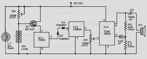
This is a simple Smoke Detector circuit based on a LDR and lamp pair for sensing the fire. It uses a very simple approach to detecting smoke in the air. The alarm works by sensing the smoke produced during fire. The circuit produces an audible alarm when the fire breaks out with smoke.
Smoke Detector circuitSmoke Detector circuit using LDR

When there is no smoke the light from the bulb will be directly falling on the LDR.The LDR resistance will be low and so the voltage across it (below .6V).The transistor will be OFF and nothing happens. When there is sufficient smoke to mask the light from falling on LDR, the LDR resistance increases and so do the voltage across it.Now the transistor will switch to ON.This gives power to the IC1 and it outputs 5V.This powers the tone generator IC2 to play a music.This music will be amplified by IC3 to drive the speaker.

The diode D1 and D2 in combination drops 1.4 V to give the rated voltage (3.5V ) to UM66 .UM 66 cannot withstand more than 4V.

12VDC to 220VAC Inverter Circuit Using IC 555

type='html'>This is a simple 12VDC to 220AC inverter circuit that can be used produces an AC output at line frequency and 220AC or different voltage by selecting transformer T1. The 555 IC is configured as a low-frequency oscillator, tunable over the frequency range of 50 to 60 Hz by Frequency potentiometer R4.
12VDC to 220VAC Inverter Circuit 12VDC to 220VAC Inverter Circuit

The 555 feeds its output (amplified by Q1 and Q2) to the input of transformer T1, a reverse-connected filament transformer with the necessary step-up turns ratio. Capacitor C4 and coil L1 filter the input to T1, assuring that it is effectively a sine wave. Adjust the value of T1 to your voltage. The output ( in watts) is up to you by selecting different components.

Input voltage is anywhere from +5V to +15Volt DC, adjust the 2700uF cap's working voltage accordingly. Replacement types for Q1 are: TIP41B, TIP41C, NTE196, ECG196, etc. Replacement types for Q2 are: TIP42B, TIP42C, NTE197, ECG197, etc.

Sunday, June 24, 2012

Stepper Motor Controller using IC 4027

The stepper controller circuit is very interesting, since most lines the step motor controllers are very expensive. The circuit is made ​​of standard components and can easily be adjusted by a computer. If you cheap surplus transistors and stepper motors, the price of the circuit can be less than $ 15.
Stepper Motor Controller Circuit using IC 4027
This stepper controller circuit shown here can used to control the unipolar stepper motor, the which has four coils. The stepper controller circuit can drive for a motor current of up to about 500 MAMP / Winding by Suitable heat sinks for the SL-100 In higher currents seem 2N3055 power transistors can be used as darlington pair along with the SL-100. All diodes are used to protect the transistor from back current transients.

List Componet
R1, R2 ,R3, R4: 1K 1/4W Resistor
D1, D2, D3, D4: 1N4002 Silicon Diode
Q1, Q2, Q3, Q4: TIP31 NPN Transistor (See Notes) TIP41, 2N3055
U1 : 4070 CMOS XOR
U2 : 4027 CMOS JK Flip-Flop
S1 : SPDT Switch
 
Notes: 
1. You should be able to substitute any standard (2N3055, etc.) power transistor for Q1-Q4.
2. Every time the STEP line is pulsed, the motor moves one step.
3. S1 changes the motors direction.
4027 CMOS JK Flip-Flop IC  Pinout
4070 CMOS XOR IC Pinout