Showing posts with label Seven. Show all posts

Sunday, August 12, 2012

Seven Segment

type='html'>

Seven Segment is 8 pieces of LED array is arranged in such a way that was shaping up to 7 segments and 1 point that can be used to show the pattern numbers and some letters. there are two types of seven-segment LED Seven segment of the Common Anode (CA) and Common Cathode (CC).
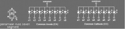
Seven Segment


On picture above is the layout, naming seven segment each segment and 8 illustrate the fruit is packed as the LED array LED Common Anoda (CA) and an array of LED Common Cathode (CC).
segemen seven controllers can be done directly, or through a pattern such as a driver IC 74LS47 to seven segment CA and 74LS48 to seven segment CC.

To save power it is, the LED does not continuously switched on the frequency of 85Hz to 100Hz. How this can be applied to the output enable series of flow control as AC generators, either sine, square, triangle or trapesium. But rarely on the set of digital more often use the AC current wave form of a square, it This is because the series of digital only have 2 types of condition (logic 0 and logic 1) and simulate the process square wave can be easily carried out, namely the exchange of a logic 1 to logic 0 periodically at a certain frequency.


Rangkaian Antarmuka Seven Segmen Dengan AT89S51/52

type='html'>
Data that is processed mikrokontroler data hexa, to be shown on seven segment we can use dekoder hexa to the sevent segment or through the conversion program, for konveri, we can use the system look up table program we need a conversion table, table is as follows:

Place the module with mikrokontroler seven segment connecting module on port 1 and 3, do not look up inverted. Seven segment that is in use CA (Common Anode), thus need to be given to set the logic 0.
Antarmuka Seven Segmen-AT89S51/52Scheme of the Seven-segment

Antarmuka Seven Segmen-AT89S51/52The Switch scheme Electronics

Antarmuka Seven Segmen-AT89S51/52
;=================================================
;PROGRAM To turn 4X 7SEGMENT COMMON ANODA
;=================================================
ORG 00H
MULAI:
MOV P1,#0C7H ;display, data 0
CLR P3.4 ;Turn on COMMON 1
CALL DELAY ;Delay
SETB P3.4 ; turn off COMMON 1
CALL DELAY ;Delay
MOV P1,#040H ;display, data 1
CLR P3.5
CALL DELAY
SETB P3.5
CALL DELAY
MOV P1,#042H ;display, data 2
CLR P3.6
CALL DELAY
SETB P3.6
CALL DELAY
MOV P1,#050H ;display, data 3
CLR P3.7
CALL DELAY
SETB P3.7
CALL DELAY
AJMP MULAI
DELAY: ;Pause THIS USED 7SEGMENT To be invisibl
MOV R1,#1
DELAY1: DJNZ R0,$
DJNZ R1,DELAY1
RET
END

Friday, August 10, 2012

Rangkaian Counter Up|Down Dengan seven segment

type='html'>Counter up/Down Dengan seven segment Desimal

This circuit can be used for many purposes. Applications ranging from simple bottles in the belt, display a number in the queue physician practices, the timer display for competition pool, until a little complicated to show the amount of rotation in one minute lap machine.


Important components in the Circuit is the following simple counter 74LS192, and have display driver IC 74LS47 (BCD to 7 segment driver) and the indicator 7 segment LED display common anode. In fact there are other census, such as 4-bit binary counter which can be up to 16 tattoo, but here is the census that is used 10 (decade counter) would be made because the tool is the census decimal.

Main component is an IC 74LS192 up / down decade counter, which is a component that can make a census to 10 (0 to 9) up and down. Component 16 is quite a lot of pins can be found in electronics parts stores. 74LS192 built with some of JK flip-flop and gate-gate logic. Logic transition from 0 to 1 (Low to High) at the UP pin (pin 14), the output BCD (binary code decimal) QA, QB, QC and QD Ascending 1 digits.

Similarly if there is a logic transition on the 0 to 1 DN pin (pin 4), the BCD output down 1 digit. It is a good idea if you explained a little about the rules of the BCD, as there is on the table. This is shown in the table 4-bit binary code QD .. QA-me representasikan code decimal from 0 to 9.

So that can be understood by those who view it, binary code is converted to a 7-segment LED drive by using the IC 74LS47 component. Thus, this Circuit can display the corresponding decimal number. This Circuit is used in the 7 segment LED Anoda Common, where all anoda of each LED segment is connected to one and the Vcc supply. To turn one segment, 7 segment LED pins that must be sinks (short) to ground through a resistor. Resistor that is used is 100 Ohm, and this is enough light to light this LED segment.
Counter Up|Down CircuitSkema Rangkaian Counter up/Down 7 segment Desimal


IC 74LS192 also equipped with a CO output pin (Carry Out) and BO (borrow Out) that each is normally high and work separately. Decimal output transition from 0 to 9 (counting up) will trigger pin CO-issued credit 0 to 1 (Low to High). On the transition from decimal 0 to 9 (counting down), a trigger pin BO-issued credit 0 to 1. Thus, the two outputs can be used as a clock trigger level for the next census. As an example in the Circuit-1 below, 2 units in the IC 74LS192-Cascade to make a census of tens of value and unit. Readers can easily stay on if the census level necessary to create value for the next hundreds, thousands and so on.

Rangkaian Couter Desimal of census work if akan CLR pin = 0 (low). For the input port RESET must be given in the ground or logic 0 in normal circumstances. Reset (display shows the decimal number 0) applies if the CLR pin (pin 14) is a transition from logic 0 to 1. Similarly with the pin and pin UP DN, akan work (counter rise / down) only if there is a transition from 0 to 1 on this pin. Readers need to add aCircuit of switch (key) to a trigger-counter (up / down) and Reset.

Sunday, July 15, 2012

Rangkaian Decoder Seven Segmen 5 Bit

type='html'>
This decoder circuit also serves to change the 5-bit binary numbers to decimal to be displayed by seven segments. This decoder has a 5 pin input PA, PB, PC, PD PE and 14 pin output marked a, b, c, d, e, f and g.

For example, if the input PA, PB, PC, PD, PE = 11 01 0, then after the translated by the decoder will produce numbers a, b, c, d, e, f, g (MSD) = 10 0 1 1 1 1 and a, b, c, d, e, f, g (LSB) = 0 0 1 0 0 1 0. These numbers indicate that the negative pole (cathode) of the LED in a particular segment of a low voltage bias (0) so that the lights forming the number "12" on the seven-segment display devices. For more details can be seen in the picture

Rangkaian Decoder Seven Segmen 5 BitRangkaian Decoder Seven Segmen 5 Bit

In the circuit above using Seven Segment (7 Segment ) commond anode type. The principle works is, if the input pin Seven Segment a, b, c, d, e, f, g given voltage 0 volts, the LED on the Seven Segment props will be forward biased and turned to form a specific figure.

The seven segments can also be supplied with higher voltage (up to 18 V) but you have to replace the R 22 ohm with a greater value; morever, a suitable mast Rext be Chosen

Here is the truth table of the IC TDA4092 decoder

Absolute maximum rating IC TDA4092
  • Supply voltage…………….... 10 V
  • Input voltage……………….. .10 V
  • Off state output voltage…...... 20 V
  • Output current………………. 22 V
  • Total power dissipation ….. ... 0.8 mW
  • Storage and junction storage… -25 to 150 C
  • Operating temperature………. 0 to 70 C

74LS47|Decoder BCD 4-bit to Seven Segment

type='html'>Decoder BCD 4-bit to Seven Segment

decoder is a logic integrated circuit which serves to show the binary codes into signals that can be responded to visual. In accordance with a variety of ways encoding, then one can find various types of decoder, which one of them to the channel decoder output BCD seven segment

Types of BCD decoder into seven segments there are two kinds namely: which decoder functions for driving seven segment common anode mode, and decoder that functions for driving seven segment common cathode mode. but in this post we only present the common cathode mode decoder using IC 74LS47. The 74LS47 is usually used to display data from counter IC which then displayed on the seven segments.

The IC 74LS47 Feature active-low outputs designed for driving common-anode seven segment leds. The Schematic diagram of the 74LS47 is used to control the seven segments in the show on the image below

Rangkaian Decoder BCD 4-bit to Seven Segment 74LS47Skema Rangkaian Decoder BCD 4-bit to Seven Segment 74LS47


Note:
  • (BI’) must be hight “1” when output function 0 throuht 15 are desired. The (RBI’) must be hight “1” if blanking of decimal zero is not desired.
  • When (BI’) low “0” all segment outputs are off regardless of the omy other input
  • (RBI’) adn input (ABCD) are low “0” with the lamp test hight, all segment outputs go off
  • (BI/RBO’) hight and a low is applied to the lamp-test input, all segment outputa are on
for more details you can using the truth table of the IC 74LS47