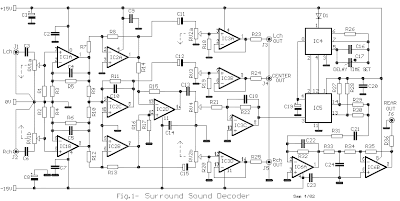
This circuit has been created to design a decoder circuit that will operate in a module that would produce an audio surround sound.

The operation of the above circuits starts as the stereo sound signal transports surround sound information on the master volume part of the circuit. This will drive the Left channel Lch attached to Model TL072 IC1A and IC1b in which Right channel Rch is attached. The outputs on these operational amplifiers would serve as the input buffer to the following stages of the circuit. IC2C is responsible for summing up the signals from the left and right channels that will power the central loudspeaker output while IC2D is responsible for increasing the phase difference between left and right channels which is encoded in the two channels and will be fed to the rear loudspeakers. It is necessary to ensure that the negative terminals between the rear speaker is not earthed because they will simply function in parallel with the main speakers.
The output of IC2D will power regulated delay unit of audio to the rear loudspeakers. This would lead to the creation of proper sense of spacing in accordance to the size of the room. This will incorporate op-amp sound delay signal IC5 MN3004 which has 512 stages. Since IC4 MN3101 is a clocking signal, it provides timing to IC5 as it functions as an oscillator in the circuit. Variable capacitor C17 regulates the delay time in the circuit. The presence of filters in the circuit is for the purpose of preventing noise that will be produced during the process. These filters can be regulated to cut the frequencies above 8 KHz and under 100 Hz, to be able to drive the rear speaker. The rear loudspeaker is small in size because its input is encoded with a bandwidth of 100 Hz up to 8 KHz. The filters are built around the IC6A/B which is also an output buffer. A potentiometer is placed in every output to aid in the adjustment and regulation of loudspeakers and amplifiers. The supplied power in the circuit is 15 V and every output can drive a single power amplifier.
List Compoment
R1-2-7-8-12-13-18-19-20 : 47Kohm
R3-4-5-6-21-22-34-35 : 10Kohm
R9-10-11-14-15-16-17 : 15Kohm
R23-24-25-33-36 : 100ohm
R26-27-28-31-32 : 100Kohm
R29-30 : 5.6Kohm
C1-8 : 47uF/25V
C2-7-9-14-23 : 47nF
C3-6 : 1uF/100V
C4-5-10 : 33pF
C11-12-15 : 10uF/25V
C13 : 82nF
C16 : 18pF
C17 : 100pF mini adjustable capacitor
C18 : 2.2nF
C19 : 4.7uF/25V
C20 : 100nF
C21 : 10nF
C22 : 180pF
C24 : 150nF
RV1-RV2 : 2 X 10Kohm Log. pot.
RV3-4 : 10K Log pot.
D1 : 1N4148
IC1-6 : TL072
IC2-3 : TL074
IC4 : MN3101
IC5 : MN3004
This Audio Surround Decoder circuit from www.circuit-projects.com

No comments:
Post a Comment