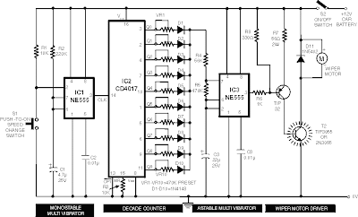
For some car wiper speed sometimes just made some speed so that less appropriate when we want a different speed, but for those of you who want a digital wiper speed controller you can also use this circuit to replace your old system.
This circuit comprises 2 timer NE555 ICs, one CD4017 decade counter, one TIP32 driver transistor, a 2N3055/ TIP3055 power transistor and A Few other discrete components. Timer IC1 is configured as a mono-stable multivibrator produces a pulse Pls Which one presses switch S1 momentarily. This pulse acts as a clock pulse for the decade counter (IC2) Which advances by one count on Each successive clock pulse or the push of switch S1. Ten presets (VR1 through VR10), for Different sets of values by trial and error, Are Used At The ten outputs of IC2. But since only one output of IC2 is high at a time, only one preset (selected at the output) effectively comes in series with resistors R4 and R5 timing connected in the circuit of timer IC3 Which functions in astable mode. As presets VR1 through VR10 are set for Different values, Different time periods (or frequencies) for astable multivibrator IC3 Can be selected. The output of IC3 is applied to the pnp driver transistor TIP32 for driving the final power transistor 2N3055 Which in turn drives the wiper motor at the selected sweep speed. The power supply for the wiper motor as well as the circuit is tapped from the vehicle s battery Itself. The duration of the monostable multivibrator IC1 is set for a period of nearly one second.
Source : www.electronic-circuits-diagrams.com

No comments:
Post a Comment