Showing posts with label Regulator. Show all posts

Thursday, August 9, 2012

Rangkaian Regulator menggunakan Diode Zener

type='html'>Regulator is a circuit of regulations or the voltage output from a ration resources so that the effects of increased tension or decrease in net does not affect the voltage ration power to be so stable.

Rangkaian Dasar Regulator Diode Zener

Simple circuit regulator , working on the zener breakdown voltage so that it produces the same output with the zener voltage, however, this circuit is only useful if the current burden of not more than 50mA. simple circuit regulator using zener diode can you see in the circuit under the scheme

Circuit of regulator using diode Zener
Skema rangkaian Regulator Dioda Zener dasar

voltage output:
Rangkaian regulator Diode ZenerResistor value
Circuit of regulator using diode ZenerWith this design approach, you must check the power ratings of your output resistor and Zener diode to make sure they are able to handle the power requirements.

The power rating load of resistor and zener diode must be at least of they are able to handle
Rangkaian Regulator Zener dengan Transistor

Regulator This is basically the zener regulator is configured with an NPN transistor to produce a large amount of cash. V BE is the base-voltage emitor of the size of the transistor Q1 between 0.2 - 0.7 volt depending on the type of transistor used. By ignoring the current IB flowing in the transistor base, can be counted prisoners of R2 that is needed is:

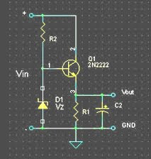
Circuit of regulator using diode Zener
Rangkaian regulator Diode Zener
Skema rangkaian Regulator menggunakan Diode Zener

Iz is a minimum flow required by dioda to reach the zener voltage is zener breakdown. Large currents can be known from the datasheet that the size of the approximately 20 mA

If the required portion of greater flow, calculation of base flow in the IB on the circuit can not be ignored anymore. As is known, large currents IC akan proportionate flow straight to the IB or with the right formula

Rangkaian regulator Diode ZenerFor such purpose, the transistor Q1 can be replaced with a Darlington tansistor usually have a value of b is quite large. With the Darlington transistor, the base flow of small currents can produce a larger IC

Rangkaian Regulator menggunakan Op-Amp

type='html'>Regulator is a series of regulations or the voltage output from power so that a portion darinaik effects or voltage drop in net does not affect the voltage ration power to be so stable.


Regular circuit of regulators have been good if the ripple voltage is small, but there is a problem of stability. If the voltage PLN rise /down, then the output voltage is also will be rise /donw. regular circuit of regulators, if the current of the larger, the dc voltage output is also down. For some applications this voltage change will very disrupt.

Rangkaian Regulator menggunakan Op-Amp


Regulator using Op-AmpSkema rangkaian regulator menggunakan OP-Amp

Technical regulations that better is to use the Op-Amp for a drive-transistor Q. Dioda zener here do not give directly to the bait transistor Q, but as a reference voltage for the Op-Amp IC1. Feedback on the negative pin Op-amp is a snippet from the voltage regulator out, namely:
Regulator using Op-AmpIf the voltage V out exit Ascending, voltage V in (-) also Ascending until this voltage is the same as the reference voltage Vz. Likewise if the voltage V out decreases exit, for example because of supply current to the load increases, Op-amp will maintain stability in the V reference point z with the current IB to the transistor Q1 so that at any time in the Op-amp maintain stability:
Regulator using Op-Amp
Ignore the VBE voltage transistor Q1 and mensubsitusi formula, obtained by mathematical relationships
Regulator using Op-Amp
In the circuit of regulator Op-Amp of this output voltage can be adjusted with the set of R1 and R2.

Wednesday, August 8, 2012

Rangkaian +5V Switching regulator

type='html'>Rangkaian +5V Switching regulator used LM2575-5.0. You can make the stable voltage by using the 3 terminal regulator like LM317. However, because the output electric current and the inputted electric current are the same approximately, the difference between the input electric power (The input voltage x The input electric current) and the output power (The output voltage x The output current) is consumed as the heat with the regulator. Because it is, the efficiency isn’t good. In case of the switching regulator, it inputs only the electric power which is necessary to output from the input by the switching operation. Because it is, there is little electric power to consume with the regulator and it is efficient.

Switching regulator
Skema Rangkaian +5V Switching regulator

DC to DC step down voltage regulator. Wide input voltage 8Vdc to 40Vdc.
  • LM2575-3.3 (3.3Vdc output)
  • LM2575-5.0 (5Vdc output)
  • LM2575-12 (12Vdc output)
  • LM2575-15 (15Vdc output)
  • LM2575-ADJ (1.23Vdc to 37Vdc output)

The switching regulator which introduces in this page is the step down type and is the one to get the output voltage which is lower than the input voltage. As for the regulator which uses this time, the output is 5-V fixation.
The switching regulator of the step up type can be made the voltage which is higher than the input voltage.


Kegunaan IC LM2575

The LM2575 series of regulators are monolithic integrated circuits that provide all the active functions for a step-down (buck) switching regulator, capable of driving a 1A load with excellent line and load regulation. These devices are available in fixed output voltages of 3.3V, 5V, 12V, 15V, and an adjustable output version.

Requiring a minimum number of external components, these regulators are simple to use and include internal frequency compensation and a fixed-frequency oscillator.

The LM2575 series offers a high-efficiency replacement for popular three-terminal linear regulators. It substantially reduces the size of the heat sink, and in many cases no heat sink is required.

A standard series of inductors optimized for use with the LM2575 are available from several different manufacturers. This feature greatly simplifies the design of switch-mode power supplies.

Other features include a guaranteed ±4% tolerance on output voltage within specified input voltages and output load conditions, and ±10% on the oscillator frequency. External shutdown is included, featuring 50 μA (typical) standby current. The output switch includes cycle-by-cycle current limiting, as well as thermal shutdown for full protection under fault conditions.

Saturday, August 4, 2012

Rangkaian Car Regulator Converter

type='html'>
This is car regulator 12 VDC to 9 VDC converters side for audio, playstation,DVD,etc... The regulator designed for 12DC to 9DC converters that we bring to our design circuit . They are all effective in Switch Mode Power Supplies regulated output. We have developed a series of DC-DC power supply models ranging from 1 watt to 500 watts, which we incorporated into the new controller of DC converters. We are also developing new areas whenever necessary to meet customer requirements. We can provide some custom products that changes on the following products and fully custom DC-DC, new products, such as DC Battery Backup Power Supplies.


car regulator converter
Note:
Assemble the circuit on a good quality PCB.
The Q1 ECG184 must be mounted on heat sinks.


list Componet

C1: 1000uf/16v
C2: 100uf/16v
C3: 330nf
R1: 560 ohm, Resistor 1 watt
Z1: 9.1 Volt, diode zener
Q1: EGC184.
.

Tuesday, July 31, 2012

+12Volt|-12Volt Dual Regulator Power Supplay

type='html'>This is of a dual regulated that provides +12V and -12V from the AC mains. A regulator like this is a very essential tool on the work bench of an electronic hobbyist.

Transformer T1 steps down the AC mains voltage and diodes D1, D2, D3 and D4 does the job of rectification. Capacitors C1 and C2 does of filtering.C3, C4, C7and C8 are decoupling capacitors. IC 7812 and 7912 are used for the purpose of voltage regulation in which the former is a positive 12V regulator and later is a negative 12V regulator. The output of 7812 will be +12V and that of 7912 will be -12V.


rangkaian Dual Regulator Power Supplay Skema rangkaian Dual Regulator Power Supplay


IC regulator 78xx


IC regulator 79xx


Note:
  • Use Transformer 15-0-15 V, 1A secondary step-down transformer.
  • Capacitor C1,C2,C5 and C6 must be rated 50V or more.

IC regulator 78xx (7812) Description

The LM78XX series of three terminal regulators is available with several fixed output voltages making them useful in a wide range of applications. One of these is local on card regulation, eliminating the distribution problems associated with single point regulation.

Maximum Ratings
  • Input Voltage (VO = 5V, 12V and 15V) : 35V
  • Operating Temperature Range (TA) : 0°C to +70°C
  • Maximum Junction Temperature : 150°C
  • Storage Temperature Range −65°C to +150°C
  • Lead Temperature (Soldering, 10 sec.)

IC regulator 79xx (7912) Description

The LM79XX series of three-terminal negative regulators are available with several fixed output voltages, making them useful in a wide range of applications. Each type employs internal current limiting, thermal shutdown and safe operating area protection, making it essentially indestructible.


Maximum Ratings
  • Input Voltage (VO = -5V, to 15V) : 35V
  • Operating Temperature Range (TA) : 0°C to +70°C
  • Maximum Junction Temperature : 150°C
  • Storage Temperature Range −65°C to +150°C
  • Lead Temperature (Soldering, 10 sec.)
.

Saturday, July 28, 2012

Regulator 5 volt Meggunakan IC 7805

type='html'>Regulator 5 volt IC 7805

The IC 7805 provides circuit designers with an easy way to regulate DC voltages to 5v. Encapsulated in a single chip/package (IC), the 7805 is a positive voltage DC regulator that has only 3 terminals. They are: Input voltage, Ground, Output Voltage.

rangkaian regulator 5 voltSkema rangkaian regulator 5 volt


Layout IC 7805


Although the 7805 were primarily designed for a fixed-voltage output (5V), it is indeed possible to use external components in order to obtain DC output voltages of: 5V, 6V, 8V, 9V, 10V, 12V, 15V, 18V, 20V, 24V. Note that the input voltage must, of course, be greater that the required output voltage, so that it can be regulated downwards


Features IC regulator 7805
• Output Current up to 1A
• Output Voltages of 5 Volt
• Thermal Overload Protection
• Short Circuit Protection
• Output Transistor Safe Operating Area Protection

Data max IC 7805
Input Voltage........................................ 35
Thermal Resistance Junction-Cases (TO-220)40......... 5 °C/W
Thermal Resistance Junction-Air (TO-220)............. 65 °C/W
Operating Temperature Range (KA78XX/A/R)............. 0 ~ +125 °C
Storage Temperature Range............................ -65 ~ +150 °C.

Friday, July 13, 2012

Rangkaian Regulator 78xx (7805,7812,7815...)

type='html'>
The available voltage from a voltage source that is usually not appropriate to the needs. It is necessary for a voltage regulator that functions to maintain the constant voltage value on a certain value. Voltage regulator chip is usually a code with the 78xx or 79xx. For the 78xx series is used for DC positive voltage regulator. xx indicates the regulator output voltage. For example, the system needs is a + 5 volt positive, the regulator used is 7805. Chip regulator consists of three pins, namely input, output and ground. In this IC uses the input voltage must be greater several percent (depending on the data sheet) from the value output voltage.
search

Chip lm78xx provide facilities in the affairs regulator. price is also relatively inexpensive and easy to find in the market

body Regulator 78xx

Features important in the IC LM 78xx:
  • current up to 1A
  • Security short internal
  • Safe temperatures 0°C - 70°C
  • Temperature max 150°C

Voltage out put in the offer:
  • LM7805C 5V
  • LM7806c 6V
  • LM7808 8V
  • LM7809 9V
  • LM 7810 10V
  • LM7812C 12V
  • LM7815C 15V
  • LM7824 24V
To be able to work with both the input voltage must be greater (voltage output volt + 3) of the output voltage. Example of the 7812 then bisanya skitar input voltage 15v

Rangkaian 78xxSkema Rangkaian 78 xx

Thursday, July 12, 2012

Rangkaian Regulator IC 79xx (7905,7912,7915...)

type='html'>
The available voltage from a voltage source that is usually not appropriate to the needs. It is necessary for a voltage regulator that functions to maintain the constant voltage value on a certain value. Voltage regulator chip is usually a code with the 78xx or 79xx. For the 79xx series is used for DC negative voltage regulator. xx indicates the regulator output voltage. For example, the system needs is a -5 volt negative, the regulator used is 7905. Chip regulator consists of three pins, namely input, output and ground. In this IC uses the input voltage must be greater several percent (depending on the data sheet) from the value output voltage.


Fisik 79xx
physical 79xx regulator chip

Pin Ic 79xx

data sheet 79xx
data sheet 79xx

Thursday, June 28, 2012

Rangkaian Regulator Variable Sederhana

type='html'>
Regulator Variable Sederhana

A simple but less efficient method of controlling a DC voltage is to use a voltage divider and transistor emitter follower configuration. The figure below illustrates using a 1K pot to set the base voltage of a medium power NPN transistor.

Rangkaian Regulator Variable SederhanaSkema Rangkaian Regulator Variable Sederhana

The collector of the NPN feeds the base of a larger PNP power transistor which supplies most of the current to the load. The output voltage will be about 0.7 volts below the voltage of the wiper of the 1K pot so the output can be adjusted from 0 to the full supply voltage minus 0.7 volts. Using two transistors provides a current gain of around 1000 or more so that only a couple milliamps of current is drawn from the voltage divider to supply a couple amps of current at the output.

Note that this circuit is much less efficient than the 555 timer dimmer circuit using a variabe duty cycle switching approach. A fairly large heat sink is required to prevent the PNP power transistor from overheating. The advantage of the circuit is simplicity, and also that it doesn't generate any RF interference as a switching regulator does. The circuit can be used as a voltage regulator if the input voltage remains constant.